
Digitally tuned low power active filter

The described circuit operates as a versatile filter capable of producing low-pass, bandpass, and high-pass outputs simultaneously. This functionality is achieved through a combination of operational amplifiers (op-amps) and passive components such as resistors and capacitors, which are arranged to define the filter's response characteristics.
The constant Q design ensures that the filter maintains a consistent quality factor across its operating range, which is crucial for applications requiring precise frequency selection and bandwidth control. The Q factor of 100 indicates a narrow bandwidth, allowing for selective filtering of signals around the center frequencies of 235 Hz and 23.5 Hz, depending on the logic input level.
The gain of 100 signifies that the output signal will be amplified by this factor, enhancing the signal strength while preserving the filter's frequency response characteristics. This is particularly beneficial in applications where signal integrity is paramount, such as audio processing or sensor signal conditioning.
The filter's design can be implemented using various topologies, including Sallen-Key or multiple feedback configurations, depending on the required specifications and component availability. Careful selection of resistors and capacitors is essential to achieve the desired center frequencies and gain, and simulation tools can be employed to model the filter's performance before physical implementation.
In summary, this constant gain, constant Q, variable frequency filter is a sophisticated solution for applications needing simultaneous low-pass, bandpass, and high-pass filtering capabilities, with precise control over frequency and gain parameters.This constant gain, constant Q, variable frequency filter provides simultaneous low-pass, bandpass, and high-pass outputs with the component values shown, the center frequency will be 235 Hz and 23.5 Hz for high and low logic inputs. Respectively, Q = 100, and gain = 100.
Related Circuits
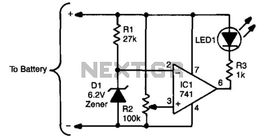
The sensing circuit consists of a 741 op-amp configured as a voltage comparator, utilizing a zener diode as a voltage reference. The op-amp is positioned as a bridge between two resistor ladders; one includes the zener reference, while the...
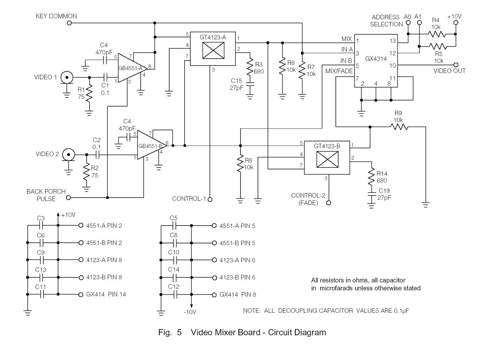
Circuit diagram of marine TV dish. Circuit diagram of marine TV dish, circuit diagram of marine TV dish, 12V DC to 120V AC inverter circuit diagram PDF, 12V DC to 120V AC inverter circuit diagram PDF. The circuit diagram for...
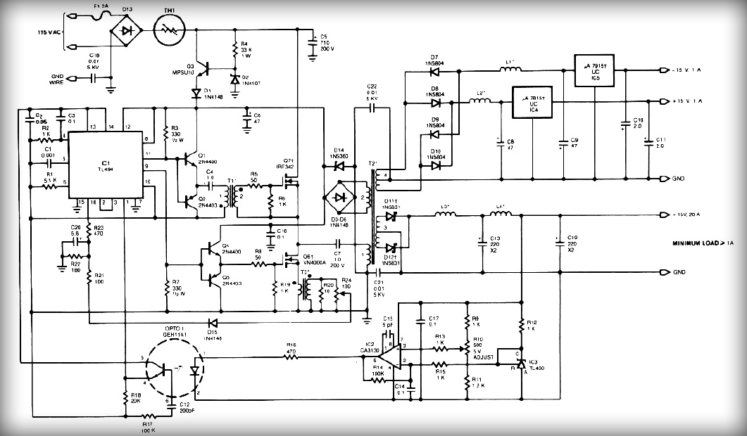
This power supply employs two VN400A 400-Volt MOSFETs arranged in a half-bridge configuration. The outputs provide +5V at 20A and +15V at 1A. Low-current outputs utilize three-terminal regulators, allowing for either 12 Volts or 15 Volts to be achieved...
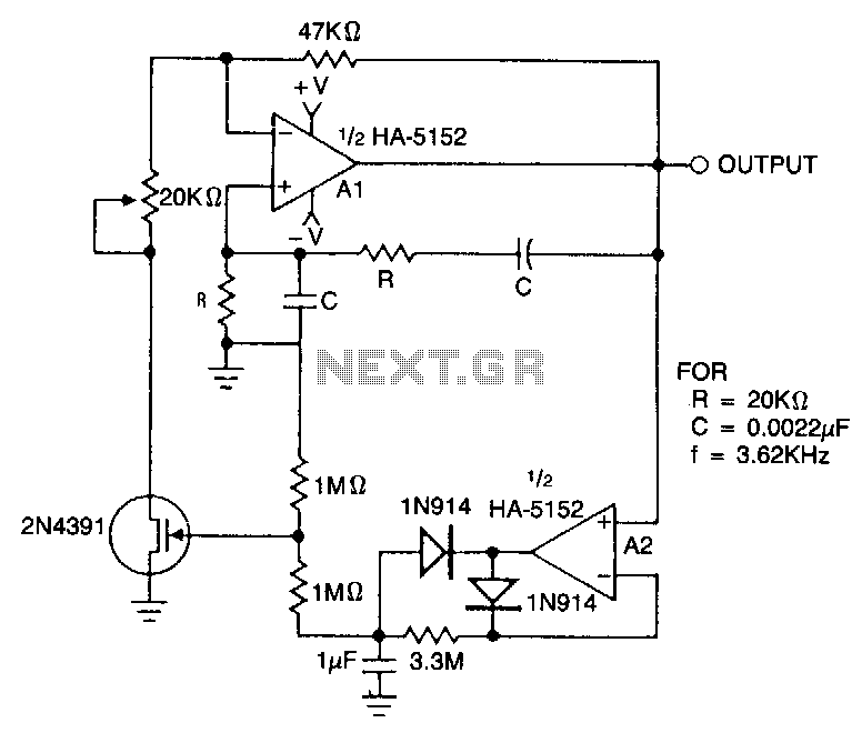
This circuit employs an HA-5152 dual operational amplifier and a field-effect transistor (FET) to create a low-voltage, low-power Wien bridge sine-wave oscillator. The frequency of oscillation is controlled by resistors and capacitors, while the FET functions as a voltage-controlled...
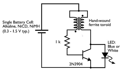
In the circuit diagram for the Joule Thief, the common point of the toroid is the connection at the top of the hand-wound ferrite toroid, located in the upper right of the diagram. This connection leads to the positive...
The power transformer features three secondary windings: 720V at 120mA center-tapped for the plate and screen supplies, 6.3V at 3.5A for the tube filament and bias power supply, and 5V at 3A (unused). Since the 5V secondary is not...