
Dimming the Nixies

The described circuit effectively manages the illumination of Nixie tubes by employing a 555 timer oscillator to control the duty cycle of the output signal. The use of a potentiometer allows for fine-tuning of the brightness, accommodating the specific needs of the Nixie tubes in use. The high voltage switching approach not only enhances the performance of the tubes but also avoids the limitations associated with simply lowering the anode voltage. The choice of transistors is critical; they must be rated for high voltage to handle the demands of the circuit while ensuring reliable operation.
The frequency adjustment capability of the circuit allows for flexibility in performance, making it suitable for various applications involving Nixie tubes. The duty cycle regulation from 5% to 95% provides a wide range of brightness settings, enabling users to achieve the desired level of illumination. This feature is particularly beneficial in scenarios where visibility under different lighting conditions is necessary.
Future enhancements could include the integration of automatic intensity regulation using photo-transistors or alternative components to adapt to ambient light changes. This would require additional circuitry, possibly involving dual FETs and an inverter stage, to create a more sophisticated control mechanism. Overall, the circuit presents a robust solution for effectively driving Nixie tubes while maintaining their operational integrity and visual appeal.Fact is that the Nixies need a particular cathode current to entirely light up the cathode at all. If you just reduce the anode voltage the current through the anode resistor drops and so does the cathode current. Up to a certain point where the cathode is only partially covered with the discharge glow - or doesn`t come on at all.
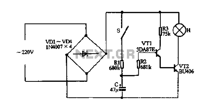
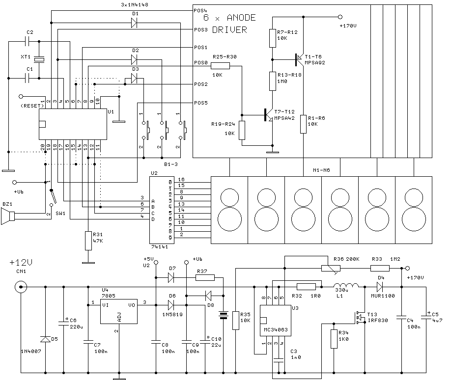
Both is not what we wanted, right So here is my approach that is a bit more complicated but seems to work fine. At least for my taste better than just reducing the anode voltage. Your individual mileage may vary however. The circuit shown above is a simple oscillator with a 555 chip. The only uncommon part of the layout is the 1M Ohm Potentiometer and the two diodes. This part of the circuit allows to vary the duty-cycle of the output signal between 5 and 95 percent. The transistor in the upper part is wired into the high voltage supply line between power supply and the nixie anode resistors.
The 555 is driving another transistor that simply cuts off the voltage on the base of that "main" transistor. Result: the lower the duty cycle of the 555 output signal, the longer is the conductive period of the main transistor - during which the full current flows through the anode resistors.
The trick is, that the high voltage is switched and not regulated. The component values in the schematic allow a frequency variation between 3 - 8. 5 ms (about 117 - 330 Hz) and the best results with a set of ZM1080s is at about 3. 5 ms (285 Hz). Here the regulation of the duty cycle works from 5 to 95 %, where 95% is pretty dim, but still readable and the cathodes fully covered. The transistors must be any of the high voltage types, since it is either attached to the HV-supply or has to sink the base voltage of the main transistor.
For my prototype I picked a BU-407 as main transistor, because I had it at hand. You might come away with an even smaller one like the BF-458 or even one MPSA-42, if you don`t have 6 x ZM1040 or bigger tubes running. This circuit has its limitations of course, but it works far better than just reducing the anode voltage and current, which cannot be reduced below a certain point.
You can use a simple potentiometer with all pins at low voltage levels to set the intensity. No need to pick something isolated or something of very uncommon value. Apart from the "high complexity" you cannot use e. g. a photo-transistor for automatic regulation (dark outside = low intensity) or such. This will require some more parts. I thought about dual FETs and an inverter stage probably. I`m open for ideas here. (Grin !) If you have a "flashing dot" neon and reduced its intensity with a higher anode resistor already it may fail to operate below a certain dimming. Or flash erratically. 🔗 External reference
Related Circuits
The fade circuit controls the lighting switch depicted in Figure 1-12. The figure illustrates the light switch S, H, which is responsible for lighting. Transistors VT1 and VT2, along with RC components, comprise the fade dimming control circuit. Given...
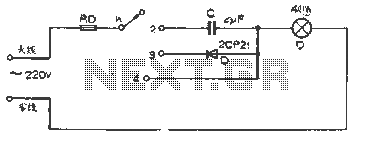
The figure illustrates a basic dimming lights circuit. The light intensity is controlled by a multi-speed control switch, designated as K. When switch K is set to position "1," the lights are turned off. In position "2," the light...
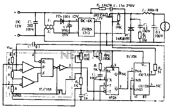
The circuit utilizes a Bute CD12V Lee power MOSFET transistor (BU1RF744) that operates in a switching mode, turning on and off repeatedly. The output voltage is influenced by the characteristics of the MOSFET, which is designed for efficient performance....
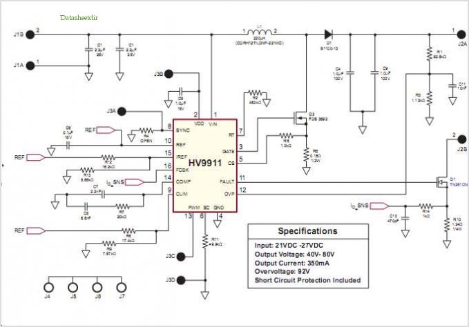
Conventionally, a MOSFET with a voltage rating of 1500V or a Half-Bridge configuration utilizing two MOSFETs rated at 800-900V is employed for Switch Mode Power Supply (SMPS) applications that require input voltages exceeding 380Vac. However, these methods present challenges,...
The clock will have 6 digits and time setting will be done by means of a few buttons. I will try to use the most common types from widely used microcontroller families of miscellaneous producers. I will write the...
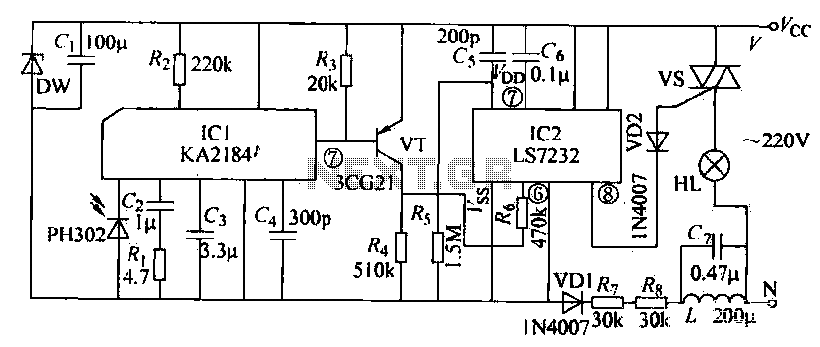
The receiving circuit operates as follows: when the infrared receiver detects a signal from the remote control transmitter, the KA2184 processes this signal, resulting in a low output at the pin. This low output is directly connected to the...