
Diode tester

The described circuit is designed to visualize the behavior of a diode through an oscilloscope. The diode's state, whether forward-biased or reverse-biased, will influence the waveform displayed on the oscilloscope. In forward bias, the diode conducts, allowing current to flow and producing a characteristic voltage drop, while in reverse bias, it blocks current flow, resulting in a different voltage characteristic.
For calibration purposes, the diode can be temporarily replaced with a 1000-ohm resistor. This substitution allows for a controlled measurement of the voltage across the resistor, which can be used to set the oscilloscope gains accurately. The objective of adjusting the oscilloscope settings to display a 45-degree line indicates that the circuit is likely intended to demonstrate a linear relationship between voltage and current under certain conditions.
The expected results, as indicated in the drawings, may include various waveforms corresponding to different states of the diode. These could range from simple linear responses to more complex nonlinear behaviors, highlighting the diode's characteristics such as forward voltage drop and reverse recovery time. The oscilloscope serves as a critical tool in visualizing these electrical phenomena, providing insight into the diode's operational limits and performance in various circuit configurations.The circuit will display curves on a scope, contingent on the state of the diode. To ' 'calibrate,'' substitute a 1000-ohm resistor for the diode and adjust the scope gains for a 45-degree line. The drawings show some expected results.
Related Circuits
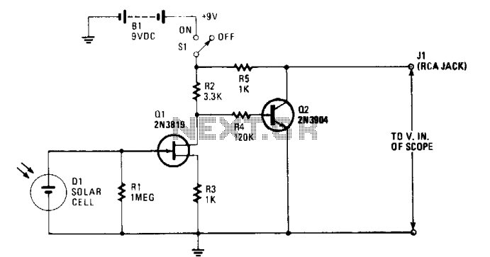
The solar cell is connected to the input of the field-effect transistor (FET), Q1, allowing it to generate a positive DC voltage at the gate when illuminated by light through the open shutter. This illumination reduces the negative gate-source...
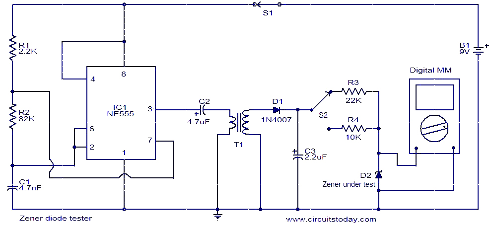
This circuit is designed for testing Zener diodes. The NE555 integrated circuit (IC1) is configured as an astable multivibrator, generating a square wave output. This output is transformed into a high voltage alternating current (AC) by transformer T1, with...
This simple circuit utilizes a 741 operational amplifier (op-amp) in differential mode to function as a continuity tester. The voltage difference between the non-inverting and inverting inputs is amplified by the op-amp's full open-loop gain. Initially, if the resistors...
Transistor Q1, a 2N3563, and its associated components form an oscillator circuit that will oscillate if, and only if, a good crystal is connected to the test clips. The output from the oscillator is then rectified by the 1N4148...
Most circuits utilize a 5 V regulated power supply for microcontrollers and sensors, as 8-bit microcontrollers operate efficiently at this voltage. The 5 V supply is adequate for powering white LEDs, thus the specific voltage requirements of individual LEDs...
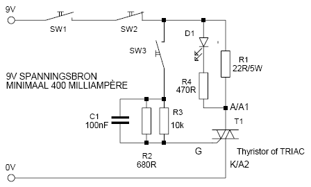
This is a simple but effective thyristor TRIAC tester. Operation at a good thyristor/triac: LED lights when SW3 is pressed. LED turns off when SW2 is pressed. If this occurs, the thyristor/triac is OK. Tip: Hirschmann clips for the...