
Switching Power Supply 14V

This switching power supply circuit operates by utilizing a Schmitt trigger oscillator to generate a square wave signal that drives a switching transistor, typically a MOSFET or bipolar junction transistor (BJT). The transistor alternately connects and disconnects the inductor to the supply voltage, allowing energy to be stored in the magnetic field of the inductor when the transistor is in the 'on' state.
When the transistor turns 'off', the magnetic energy stored in the inductor is released, causing a voltage spike. This spike is crucial as it allows the inductor to transfer energy to the load. The output voltage can be regulated based on the load resistance, which influences the amount of current flowing through the inductor and subsequently the voltage across the load.
A zener diode is incorporated into the circuit to provide voltage regulation. When the output voltage reaches approximately 14 volts, the zener diode becomes reverse-biased and effectively stops the Schmitt trigger oscillator from oscillating, thereby preventing further increases in output voltage. This feedback mechanism ensures that the power supply maintains a stable output voltage, protecting connected components from overvoltage conditions.
To adjust the output voltage levels, a voltage divider can be implemented, allowing for fine-tuning of the input to the zener diode. By changing the resistor values in the divider, various output voltages can be achieved, making the power supply versatile for different applications.
The efficiency of the power supply is approximately 80%, which is a significant factor in its design. Utilizing a high Q inductor minimizes energy losses due to core losses and skin effect, contributing to the overall performance of the circuit. This efficiency rating is essential for applications where power conservation is critical, such as in battery-operated devices or compact electronic systems.
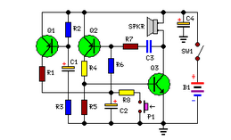
Overall, this small switching power supply design showcases a practical application of basic electronic principles, combining oscillation, energy storage, and voltage regulation to achieve a reliable power source.In this small switching power supply, a Schmitt trigger oscillator is used to drive a switching transistor that supplies current to a small inductor. Energy is stored in the inductor while the transistor is on, and released into the load circuit when the transistor switches off.
The output voltage is dependent on the load resistance and is limited by a zener diode that stops the oscillator when the voltage reaches about 14 volts. Higher or lower voltages can be obtained by adjusting the voltage divider that feeds the zener diode. The efficiency is about 80% using a high Q inductor. 🔗 External reference
Related Circuits

This circuit conducts a rapid battery test without requiring an external power supply or costly moving-coil voltmeters. It offers two testing ranges: when switch SW1 is configured as indicated in the circuit diagram, it can evaluate batteries ranging from...

The Changhong DVB-2000 digital satellite receiver features a switching power supply circuit. This circuit primarily comprises a power input section, an oscillation switching circuit, and a DC output section. The power input circuit receives 22V AC from a step-down...

This is a linear amplifier that requires advanced knowledge in electronics due to the complexity of the schematic diagram for a handmade circuit. It is advisable to redesign the schematic diagram using circuit design software such as DipTrace, Eagle,...
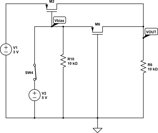
The output voltage (VOUT) is intended to be 3V when the switch is open and 5V when the switch is closed. The simulation correctly reflects the desired outcome when the switch is open; however, it does not perform as...
Simple circuit, no ICs required, 12V battery operation. This circuit was requested by several correspondents. Its purpose was to obtain more power than the standard configurations allow. This circuit design utilizes a 12V battery as the primary power source and...
This circuit is designed to indicate the power output level of any audio amplifier. It is simple, portable, and displays three power levels that can be set to any desired value. The circuit operates by utilizing a combination of resistive...