
Direction and speed control

The described circuit utilizes a Silicon Controlled Rectifier (SCR) bridge configuration to control a DC motor's operation. In this setup, the motor's field winding is connected to a rectified DC supply, providing a constant magnetic field. The SCR bridge, which consists of four SCRs arranged in a full-bridge configuration, allows for control of the armature current. By adjusting the firing angle of the SCRs, the effective voltage applied to the armature can be varied, enabling speed control.
The use of a potentiometer, designated as R1, directly influences the firing angle of the SCRs. By varying the resistance of R1, the control circuit alters the phase delay at which the SCRs are triggered, thus modifying the average voltage supplied to the armature. This adjustment not only controls the speed of the motor but also facilitates direction reversal. By changing the triggering sequence of the SCRs, the polarity of the voltage across the armature can be reversed, allowing the motor to rotate in the opposite direction.
This circuit design is particularly advantageous in applications requiring precise speed and direction control, such as in robotics and conveyor systems. The combination of a unidirectional field current and a reversible armature current provides flexibility in operation while maintaining efficient performance. Proper thermal management and component ratings must be considered to ensure reliable operation, especially in high-load scenarios.This circuit operates like the one shown in Fig, 57-4, The only differences are that the field is placed across the rectified supply and the armature is placed in the SCR bridge. Thus the field current is unidirectionali)ut armature current is reversible; consequently the motor"s direction of rotation is reversible
Potentiometer Rl controls the speed.
Related Circuits
The LM35 Smart Heater Controller Schematic features a compact circuit designed around the well-known 3-Pin Integrated Temperature Sensor LM35 (IC1) from National Semiconductor. Additionally, a widely used BiMOS Op-amp CA3140 (IC2) is employed to monitor the temperature sensor's output,...

PicCon is a PIC microcontroller based radio controller designed for hidden transmitter hunting. When combined with a radio transmitter, it will produce tone sequences and Morse code messages at user-programmed times. It is completely field programmable via DTMF tones,...

BC517 Bipolar Stepper Motor Control Circuit Diagram. Features: Each winding can carry a positive current. A bipolar motor has two windings. The BC517 bipolar stepper motor control circuit utilizes a BC517 transistor to manage the operation of a bipolar stepper...

These circuits allow an ON-ON type DPDT toggle switch to control a twin coil switch machine motor. The handle of the switch can then be used to indicate the route selected. The circuits are also able to control LEDs...

The transition from diodes to synchronous-rectification (SR) MOSFETs in the secondary circuits of flyback converters is increasing with each new generation of MOSFETs, enhancing performance with minimal or no cost increase. SR MOSFETs can offer improved efficiency compared to...
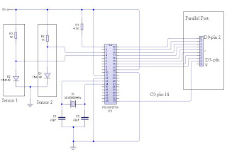
The dual-channel thermometer is a simple project based on a PIC microcontroller with ADC capabilities. It is an inexpensive thermometer that utilizes low-cost components and does not require high-sensitivity or expensive sensors. Instead, it employs a simple silicon diode...