
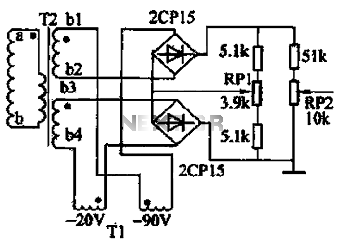
Discharge before memory circuit

The discharge before memory circuit serves a crucial role in digital electronics, particularly in applications where precise timing and state management are essential. This circuit typically incorporates a delay reset mechanism that ensures the memory element does not respond to input signals instantaneously.
The circuit design often includes a timing component, such as a resistor-capacitor (RC) network, which defines the delay period. Upon receiving an input signal, the timing mechanism initiates, allowing the circuit to maintain its output state for the duration of the delay. This ensures that transient input signals do not inadvertently alter the memory state, thus providing stability and reliability in signal processing.
In practical implementations, the delay reset circuit can be configured using various components, such as operational amplifiers, flip-flops, or dedicated timer ICs, depending on the complexity and requirements of the application. The output signal, which remains stable during the delay period, is typically connected to subsequent stages in a digital system, ensuring that downstream components receive a consistent and accurate representation of the desired state.
In summary, the discharge before memory circuit, with its delay reset functionality, is integral to achieving controlled operation in digital systems, effectively managing input signals and ensuring that memory circuits function as intended without unintended disruptions.Discharge before memory circuit Before the memory circuit is considered instantaneous action, the delay reset circuit. When the input signal to one that is action, and start ti ming, after after a delay, the circuit returns to the original state. During this period, regardless of whether the input signal is persistent, the circuit remains operation state, and the output signal.
Related Circuits
The 555 timer on the right is configured as an alarm sound generator, while the second 555 timer on the left operates as a 1 Hz astable multivibrator. The output from the left timer modulates the frequency of the...
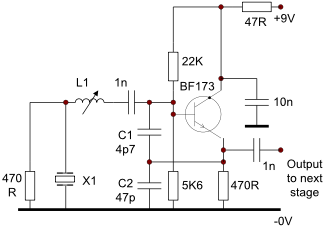
This circuit operates effectively from low frequencies up to at least 120 MHz using series resonant crystals in their fundamental or overtone mode. The output can be obtained from the feedback tap, a low impedance winding on L2, or...
This project is designed to program the 8-pin PIC12c508A and 18-pin PIC16F84 microcontroller chips to support the projects we have designed; however, it will also program a number of other 8-pin and 18-pin microcontrollers, and the full list can...
Logic testers are simple yet very useful devices for testing digital circuits. A logic probe can be designed in various ways. Logic testers, commonly referred to as logic probes, are essential tools in the field of digital electronics. These...
The closed-loop system consists of longitudinal and transverse components. The circuit operates as follows: a control circuit from the stepping motor CNC system issues a command, which the receiver detects. This signal is processed through a phase-sensitive rectifier to...
This circuit includes a Relay Timer Circuit. One of the most commonly used circuits is that of the 555 Timer integrated circuit (IC). The circuit is designed to control a relay based on a timing interval. The Relay Timer Circuit...