
Discrete Schmitt Trigger

The Schmitt trigger circuit is a fundamental electronic component utilized for signal conditioning, providing a means to convert a noisy input signal into a clean, digital output signal. The design employs positive feedback, which results in a hysteresis effect that enhances noise immunity and ensures stable switching behavior. The emitter-coupled configuration typically involves bipolar junction transistors (BJTs) arranged in a differential amplifier setup, where the output voltage is influenced by the input voltage levels.
In this configuration, the circuit operates by establishing two threshold voltage levels: an upper threshold and a lower threshold. When the input voltage exceeds the upper threshold, the output transitions to a high state. Conversely, when the input voltage drops below the lower threshold, the output returns to a low state. This hysteresis loop prevents rapid toggling of the output in response to small fluctuations in the input signal, which is particularly useful in applications such as signal processing, waveform shaping, and digital logic circuits.
The emitter-coupled design enhances the performance of the Schmitt trigger by allowing for a faster response time and improved linearity compared to other configurations. The use of BJTs in this setup provides a high input impedance, reducing the loading effect on preceding stages of the circuit. The output can be further interfaced with various digital logic families, ensuring compatibility with a wide range of electronic systems.
Overall, the Schmitt trigger circuit is an essential building block in modern electronics, serving various applications where precise signal transitions are required.This is a schmitt trigger circuit. This circuit produces a simple comparator action. It is `emitter coupled`. This circuit has a distinct hysteresis loop and.. 🔗 External reference
Related Circuits
This simple robot responds to light and avoids obstacles without the need for a microcontroller, programmer, or PC. The only unique component in the circuit is a window discriminator, which functions similarly to a window comparator. Resistors R1 and...
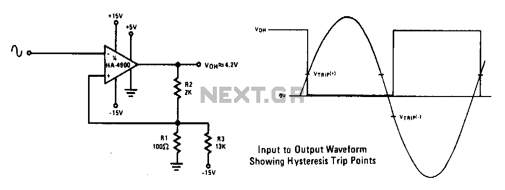
This circuit features a 100 mV hysteresis, suitable for applications demanding rapid output transition times despite slow input signals. The hysteresis loop minimizes false triggering caused by noise on the input. The accompanying waveforms illustrate the trip points established...
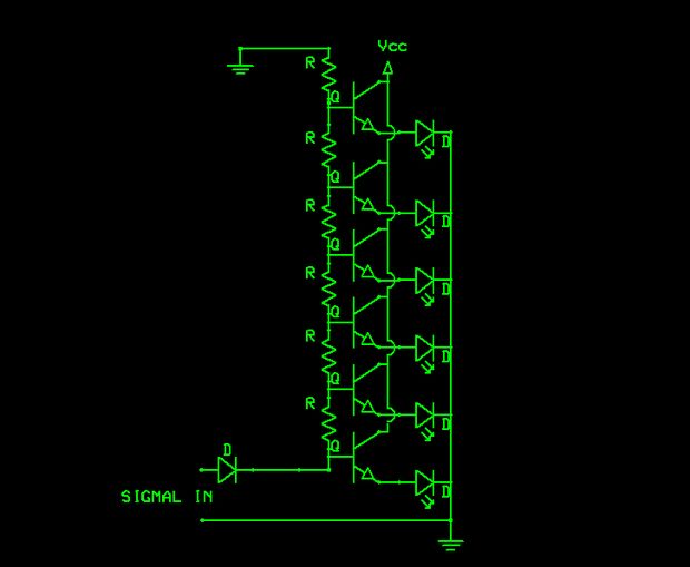
The schematic indicates that the input is routed through a voltage divider. This configuration is essential for the operation of the Schmitt triggers, which all activate under certain conditions. The voltage divider in the schematic serves to scale down the...
This Schmitt trigger circuit is emitter coupled and provides a simple comparator action. The 2N3069 JFET places very little loading on the measured input. Schmitt trigger, emitter coupled, simple comparator, 2N3565, distinct hysteresis loop. The described circuit utilizes an emitter-coupled...
An analog electronic clock that utilizes a trigger signal for operation. An analog electronic clock typically employs a trigger signal to manage its timekeeping functions. The clock's primary components include a quartz crystal oscillator, which provides a stable frequency reference,...
PWM waveforms are widely utilized to regulate the speed of DC motors. The duty cycle of the digital waveform can be established either through an adjustable analog voltage level (as seen in a NE555-based PWM generator) or through digital...