
Discrete Voltage Regulator

This discrete voltage regulator circuit is designed for applications where high current output and flexibility in voltage range are essential. The choice of the BD680 transistor allows for significant current handling, making it suitable for driving loads that require more power than typical integrated voltage regulators can provide. The ability to use high-voltage transistors further enhances the circuit's versatility, allowing it to accommodate a wider range of input voltages.
The JFET current source (T1) is critical for maintaining a stable reference voltage, ensuring that the Zener diode operates within its optimal range. The addition of C1 not only facilitates a soft start to prevent inrush current but also acts as a filter to mitigate voltage spikes and noise, which is particularly beneficial in sensitive electronic applications.
The super-Darlington configuration formed by T2 and T3 provides a robust output stage capable of driving substantial loads while maintaining the necessary voltage regulation. However, it is important to consider the trade-off introduced by the diode drop, which can affect precision applications. The optional potentiometer (P1) allows for fine-tuning of the output voltage, although careful consideration should be given to its impact on overall circuit performance.
In summary, this discrete voltage regulator circuit offers significant advantages over integrated solutions, particularly in terms of current capacity, input voltage range, and bandwidth, making it a valuable option for engineers and designers working on high-performance electronic systems.The title of this article naturally raises the question of why we think that the generous selection of fully integrated voltage regulators needs to be extended with a version constructed using discrete components. In other words, what does this circuit offer that the well-known three-leggers` don`t have To start with, we can point out that this c
ircuit is refreshingly simple for a discrete version. Three semiconductors, three resistors, a capacitor and a diode are all it needs. Of course, that`s still more components than an integrated regulator, so what exactly are the advantages of this circuit They are to be found in three areas: voltage range, bandwidth and current rating. The last of these is the primary strength of this circuit, since the maximum current depends only on the specifications of the output transistor.
With the BD680, as used here, a current of 4 A can be delivered at a collect-emitter voltage of 10 V with adequate cooling (Rth = 3. 12 K/W). The peak current is even 6 A. Try matching that with an integrated voltage regulator! The maximum input voltage is 30 V with the illustrated version of the circuit (UDSmax of T1), but this can easily be increased by using special high-voltage transistors.
The same applies to the bandwidth, which can be extended as desired, without any modifications to the circuit, by using high-speed transistors. Generally speaking, wide bandwidth is also not one of the strong points of integrated voltage regulators.
As noted, the circuit is basically very simple. A zener diode (D1) fed with a constant current of around 1mA by a JFET current source (T1) provides the reference potential. C1 is connected in parallel with D1 to provide well-behaved startup behaviour (soft start). This capacitor also provides additional buffering and decouples noise and other disturbances. The startup time is around three seconds. The only additional item that is needed for the voltage regulator is an output buffer for the reference potential.
This takes the form of a sort of super-Darlington using T2 and T3. This works very well, but has the disadvantage that the output voltage is a bit lower (one diode drop) than the Zener voltage. P1 can be added to correct this, but this does reduce the regulation of the circuit. If the voltage difference is not important, it is thus better to replace P1 with a wire jumper. The main specifications of the voltage regulator are listed in Table 1. 🔗 External reference
Related Circuits
As mentioned in the chapter about the DAC, this circuit shifts the voltage output range. The following diagram explains its operation and structure. The circuit's outputs are connected to the input pins of the power operational amplifiers. The described circuit...
Voltage to frequency conversion is highly beneficial in various applications, such as transmitting temperature measurements using standard voice radio transceivers. This circuit utilizes two CA3130 operational amplifiers, demonstrating satisfactory performance. The linearity of the voltage-frequency transfer is better than...
Incorporate a straightforward, economical jack-sensing circuit (JACKSENSE) into a DirectDrive automotive headphone amplifier to detect when headphones are plugged into the audio jack. The implementation of a jack-sensing circuit (JACKSENSE) in a DirectDrive automotive headphone amplifier is designed to enhance...
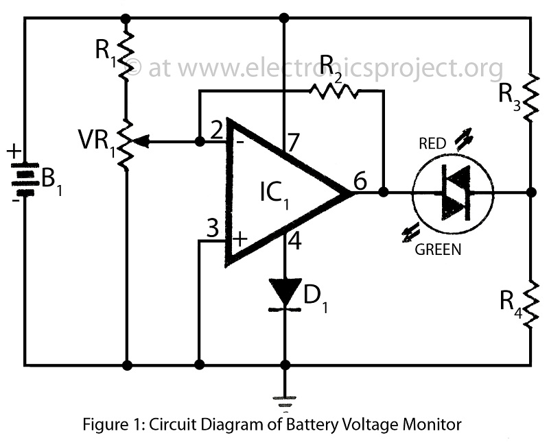
Battery voltage monitor is utilized to indicate the voltage level of a 12-volt battery circuit, specifically in a verified electronics project circuit. The battery voltage monitor circuit is designed to provide a visual representation of the voltage level of a 12-volt...
The circuit reduces voltage size or functions as a step-down voltage converter circuit, which is a DC regulated circuit model utilizing a switching converter. This design generates a specific voltage output. The step-down voltage converter, also known as a buck...
The high voltage generator depicted in figure 16-18 utilizes the 555 timer IC as its primary component. The oscillating voltage produced is enhanced through a step-up transformer. The astable multivibrator configuration comprises the 555 timer along with resistors R1...