
display and serial interfacing of
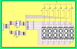
The schematic for this parking lot car counter system includes several key components that work together to achieve the desired functionality. The SN7447AN is a BCD to 7-segment latch/decoder/driver that controls the display segments based on the binary-coded decimal input from the microcontroller. The microcontroller processes the input data, which represents the number of cars detected in the parking lot, and sends this information to the SN7447AN.
The 3-to-8 decoder is used to select which segment of the display should be activated based on the binary input. This allows for efficient control of the segments, ensuring that only the necessary segments are lit up to represent the current count accurately.
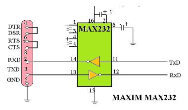
The communication between the microcontroller and the computer is facilitated through the ICL232, which translates the TTL logic levels from the microcontroller to RS-232 levels suitable for serial communication. This ensures reliable data transmission over the serial cable, which is configured in null modem mode to enable direct communication between the two devices.
The DB9 connector serves as the interface point for the serial connection, with specific pin assignments for data transmission and reception. The shorting of pins 7 and 8, as well as pins 6 and 4, establishes the necessary connections for null modem communication, allowing the devices to exchange information seamlessly.
Overall, this schematic integrates digital display technology with serial communication to create an efficient and effective solution for monitoring parking lot occupancy. The careful selection of components and their configurations ensures that the system operates reliably and accurately, providing real-time data to the control room.This hardware is used to display the number of cars in the parking lot. Basically, this board has six-segment display but using only one display can do our work. It used segment driver IC SN7447AN and 3*8 decoder to select the corresponding display. This unit is to display the number of cars in parking lot on the computer. The computer may be plac ed in any control room. Serial cable is used in null modem mode. We use the DB9 connector for serial interfacing. In null modem mode pin 7, 8 and pin 6, 4 are shorted with each other. While pin 3 is used for transmit data and pin 2 for reception. Computer and the micro-controller are connected to each other by serial port through ICL232 (IC 1), the only purpose of which is to convert the voltage levels to the compatible values. ICL232 needs to be used because the TTL and RS-232 voltage levels are different. In TTL, +5V and 0V are considered as high and low respectively, whereas for RS-232 these are 3V and +3V.
🔗 External reference
Related Circuits
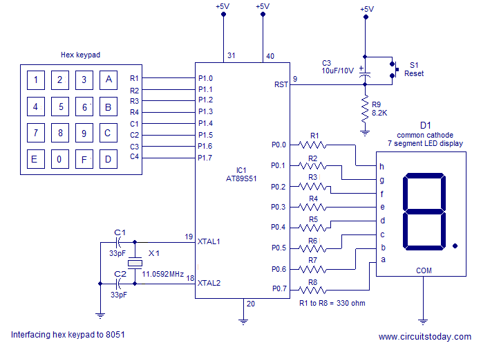
Interfacing a hex keypad to an 8051 microcontroller. The AT89S51 is utilized in this setup. A circuit diagram and assembly language program are included. A testing video is also provided. The interfacing of a hex keypad with the AT89S51 microcontroller...
A universal digital gear display that can be installed on any motorbike. This is a low-cost solution based on simple TTL digital technology without software programming. The universal digital gear display is designed for easy installation on a variety of...
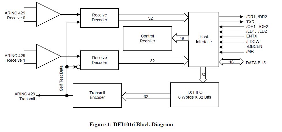
This document outlines the process of interfacing an Arduino with an ARINC 429 transceiver, illustrating the general methodology for connecting an Arduino to electronic circuits that can be applied to individual designs. The ARINC 429 bus is the predominant...
This project involves an output port expander for the 8051 microcontroller. It focuses on interfacing a large load bank with the microcontroller. In this load bank project, up to 50 solid-state relays are connected to the microcontroller using the...
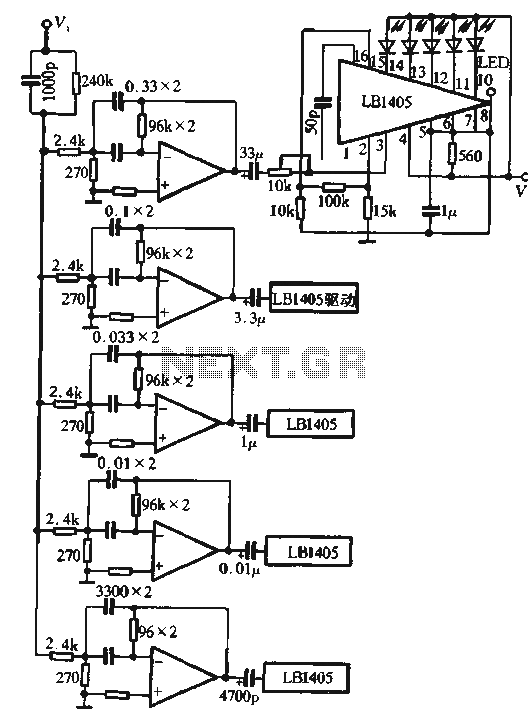
The circuit utilizes the LM324 as a band-pass filter and the LB1405 as a driver for a five-band spectrum display. The selected frequency harmonics are centered at 100 Hz, 330 Hz, 1 kHz, 3.3 kHz, and 10 kHz. The...
LED displays consist of arrays of Light Emitting Diodes (LEDs) arranged in various shapes to convey specific information. The operation of LED displays is similar to that of standard LEDs, requiring straightforward connections when sufficient microcontroller pins are available....
Warning: include(partials/cookie-banner.php): Failed to open stream: Permission denied in /var/www/html/nextgr/view-circuit.php on line 713
Warning: include(): Failed opening 'partials/cookie-banner.php' for inclusion (include_path='.:/usr/share/php') in /var/www/html/nextgr/view-circuit.php on line 713