
DISPLAY BOARD FOR RADAR GUN

The described circuit is designed to process Doppler radar signals effectively. It begins by receiving the raw Doppler signal, which is typically a low-level analog signal. The first stage of the circuit involves amplification, where the weak radar signal is boosted to a more manageable level. This amplification is critical for ensuring that the subsequent processing stages can accurately interpret the signal.
Following the amplification, the signal undergoes a limiting stage. This is essential for eliminating noise and preventing signal distortion, which can occur due to fluctuations in the input signal. By limiting the signal, the circuit ensures that only the relevant frequency components are passed on to the next stage.
The processed frequency is then directed to a counter (U4), which counts the number of cycles of the incoming signal over a specified time period. This frequency information is crucial for calculating the speed of an object based on the Doppler effect. The counter's output is subsequently fed into a display circuit composed of components DISP1, DISP2, U5, and U6. This display circuit provides a visual representation of the speed measurement, allowing users to easily read the results.
Calibration of the counter is handled by the clock circuit (U2B), which generates a precise timing reference for the counting operation. Resistors R21 and R22 play a pivotal role in this calibration process. By adjusting R21, users can modify the scaling of the readout, enabling the display to show speed in kilometers per hour or other desired units. This flexibility in calibration ensures that the circuit can be tailored to meet specific application requirements.
Overall, this circuit exemplifies a robust design for radar signal processing, featuring amplification, limiting, counting, and display capabilities, all of which are essential for accurate speed measurements in various applications.This circuit takes signal (doppler) from a radar,un, amplifies and limits it, and feeds the frequency into a counter (U4) and display circuit (DISP1, DISP2,U5,U6). Counter calibration is set by clock circuit U2B. Calibration is obtained via R21 and R22. R21 can be changed if kilometers/hour readout is desired.. 🔗 External reference
Related Circuits
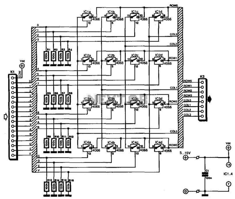
Keyboards can be classified into two categories based on the connection method of the switches: those with a common connection and those arranged in a matrix. The matrix type offers the significant advantage of minimizing the number of connections,...
A tiny sandwich flag connected perpendicular to the motor spindle aids observation of how long it takes to complete one full rotation. This worked initially, as each burst from the capacitor barely moved the flag 1/4 of a rotation....
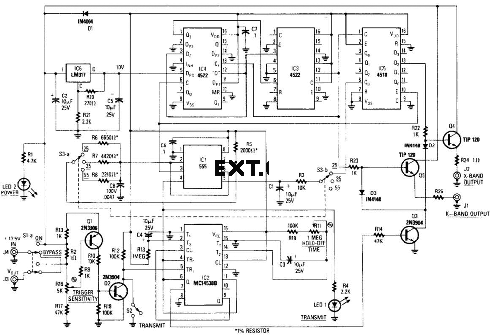
This circuit is a system designed to generate a pulsed modulation signal for a Gunn diode microwave oscillator. It features several preset speed settings (S3 a and b). A 555 timer is employed in conjunction with a frequency divider...
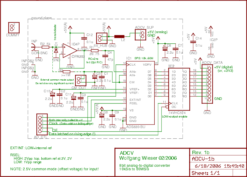
The analog input is initially connected to a fast non-inverting buffer amplifier (OPA353) configured for unity gain, which safeguards the analog-to-digital converter from out-of-range voltages. The ADS830 is an economical 8-bit analog-to-digital converter that accommodates sampling clocks ranging from...
This circuit is a Digital Radar Speedometer that measures the speed of moving objects, particularly vehicles such as cars. The speed is displayed in kilometers per hour (KPH) and features a three-digit display. The radar operates using laser reflection...

This article continues from the previous one regarding the single character LCD display using an AVR microcontroller. The prior article demonstrated how to display a single letter on an LCD. This article advances the learning process by explaining how...