
Dive Computer interface RS232

The described circuit serves as an interface for a dive computer utilizing the RS232 communication protocol, incorporating the MAX232A integrated circuit. The MAX232A is a dual voltage-level converter that facilitates communication between devices operating at different voltage levels, specifically converting TTL (Transistor-Transistor Logic) levels to RS232 levels and vice versa.
In this application, the dive computer likely operates at TTL levels (typically 0V to 5V), while the RS232 standard operates at higher voltage levels, ranging from +3V to +25V for logical '1' and -3V to -25V for logical '0'. The MAX232A enables seamless communication between the dive computer and other RS232-compliant devices, such as a PC or a data logger.
The circuit typically consists of the MAX232A chip, several external capacitors for charge pump operation, and the necessary RS232 connectors (DB9 or DB25) to interface with other devices. The external capacitors, often 1µF to 10µF, are connected to the charge pump pins of the MAX232A to generate the required positive and negative voltage levels for RS232 communication.
Pin configuration of the MAX232A is crucial for proper functionality. The chip features multiple pins designated for TTL input and output as well as RS232 output. The circuit design should ensure that the TTL signals from the dive computer are connected to the appropriate input pins of the MAX232A, while the RS232 outputs are routed to the connectors.
In practice, the circuit will require careful attention to grounding and signal integrity to avoid communication errors. Proper layout considerations, such as minimizing trace lengths and avoiding cross-talk, will enhance the reliability of data transmission in this dive computer interface.This circuit represents a Dive computer interface for RS232. Uses the MAX232A. 🔗 External reference
Related Circuits
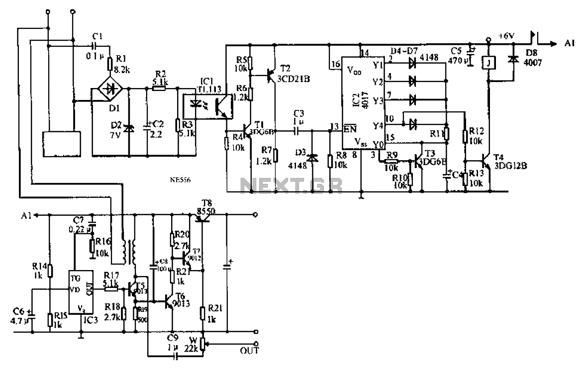
An automatic recording telephone interface circuit is presented, featuring an automatic answering and recording function that requires a reprovisioning or a small solid-state recording chip. The circuit is straightforward, with a quiescent current of less than 20 µA, allowing...
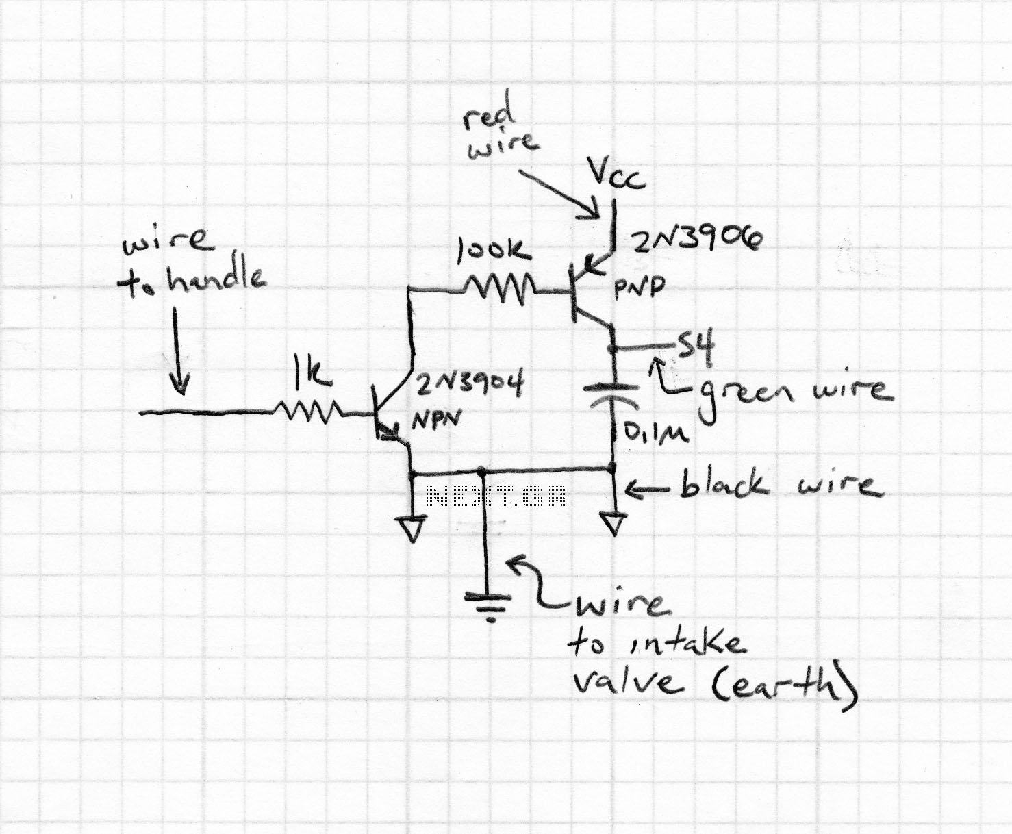
This project involves controlling an AVR microcontroller (MCU) using Visual Basic 6. The applications of this circuit are numerous, enabling the creation of various devices that require control from a Personal Computer (PC) or any circuit that collects data...
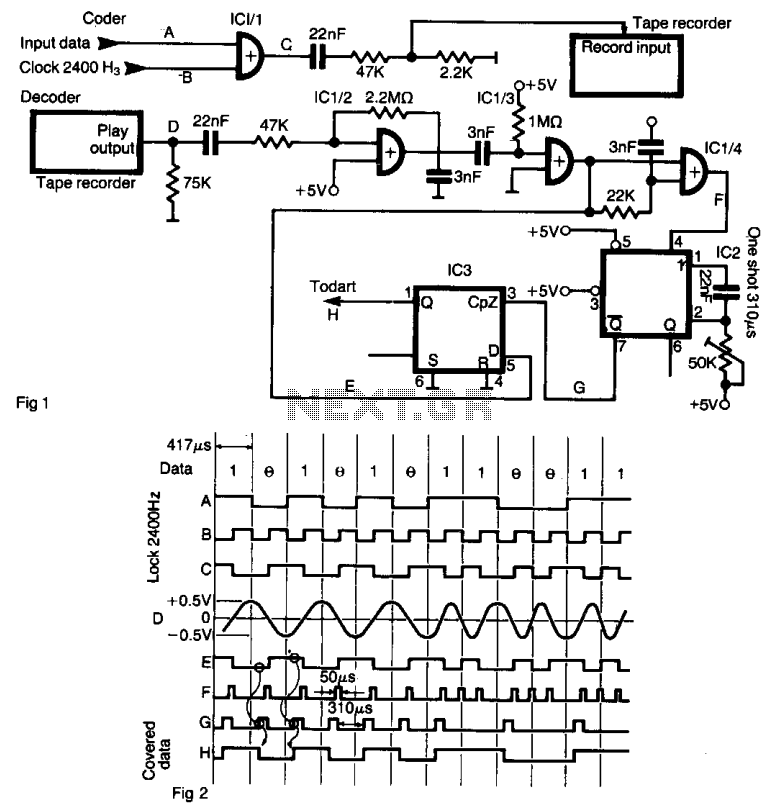
The interface enables data to be recorded on a standard tape recorder at a speed of 2400 bits per second. The serial data stream is encoded with a clock frequency of 2400 Hz using an XOR gate (IC 1/1)....

The circuit is an easy-to-build and use general-purpose Big LED with SPI serial interfacing. It is expandable for multiple digits while utilizing only three wires to receive data from any microcontroller boards. The design incorporates a serial-in-parallel-out shift register,...
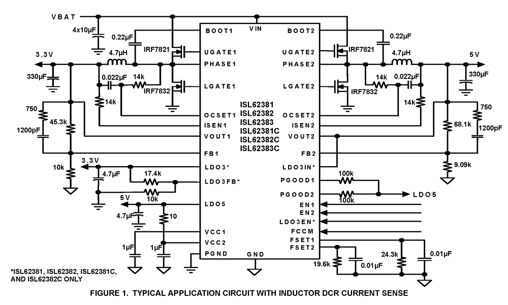
The ISL62381, ISL62382, ISL62383, ISL62381C, ISL62382C, and ISL62383C family of controllers generate supply voltages for battery-powered systems. These controllers include two pulse-width modulation (PWM) controllers, adjustable from 0.6V to 5.5V, and two linear regulators, LDO5 and LDO3, that generate...

All of ACC's repeater and remote base products support the control of synthesized remote base transceivers. One form of frequency control supported is compatible with transceivers using thumbwheel frequency selection. The controllers supply BCD (binary coded decimal) formatted data...