
DIY Crystal Oscillator Circuit

This DIY crystal oscillator circuit is designed to generate stable oscillations using a quartz crystal, which is known for its excellent frequency stability. The circuit typically consists of a few key components, including a quartz crystal, an RF transistor, resistors, and capacitors.
The choice of using a second or third harmonic crystal is crucial, as it allows the oscillator to operate at higher frequencies than the fundamental frequency of the crystal. The RF transistor amplifies the oscillations produced by the crystal, ensuring that the output signal is strong enough for further applications.
In constructing this circuit, the quartz crystal is connected in a feedback loop with the RF transistor. The feedback network comprises resistors and capacitors, which help to stabilize the oscillation frequency and control the gain of the oscillator. Proper selection of these passive components is essential for achieving the desired frequency output and maintaining signal integrity.
The oscillator can be powered by a DC voltage source, typically ranging from a few volts to a maximum specified by the transistor's ratings. The output can be taken from the collector of the transistor, which provides a high-frequency signal suitable for various applications, including signal generation, clock pulses, or as a local oscillator in RF applications.
Overall, this simple DIY crystal oscillator circuit serves as an excellent introduction to oscillator design, demonstrating the principles of frequency stability and amplification in a straightforward and accessible manner.A very simple DIY crystal oscillator circuit which use a quartz for frequency stability and a good rf transistor. Use a 2-nd or 3-rd harmonic crystal, for.. 🔗 External reference
Related Circuits
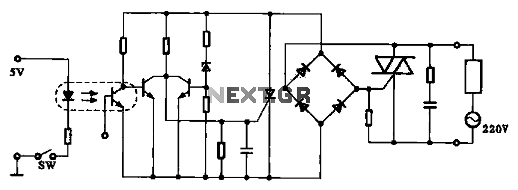
This application example illustrates a photovoltaic control circuit. In this circuit, the Triac functions as a solid-state relay, providing an AC power supply path to the load. It is designed to achieve high current control signals using a small...
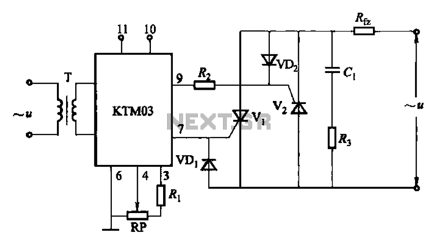
Adjustment potentiometer RP can modify the conduction angle of thyristor Vl, vz, thus altering the voltage applied across the load Rfz. The adjustment potentiometer (RP) serves a critical role in controlling the conduction angle of the thyristors Vl and vz within...
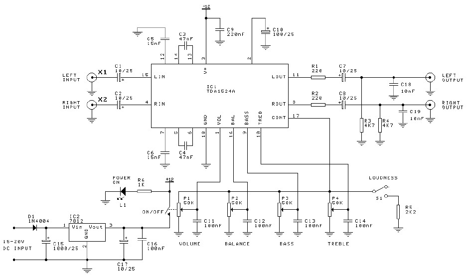
Preamplifier and tone control circuit based on the TDA1524A. The tone control circuit module is included in this preamplifier circuit, allowing for direct connection of the output channels to a stereo power audio amplifier circuit. This RIAA stereo preamplifier...
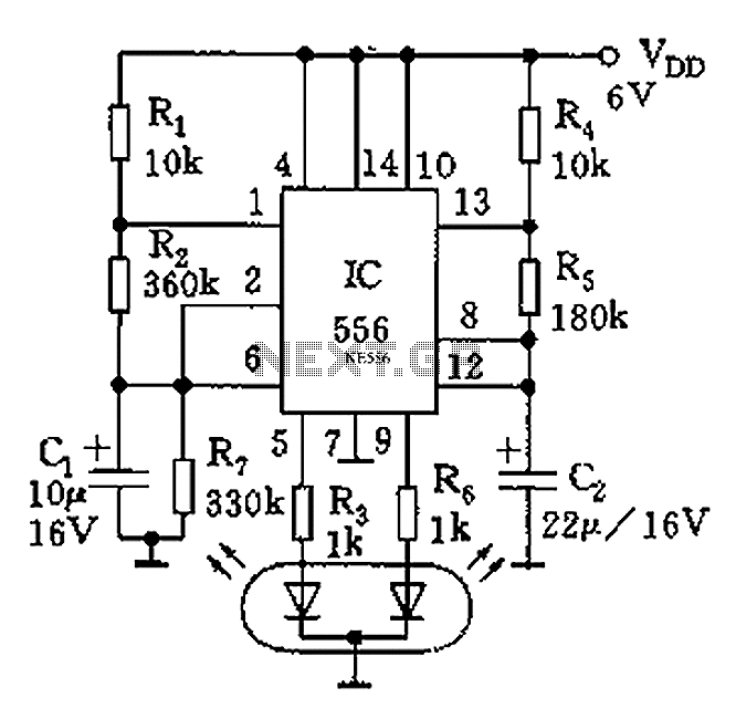
The circuit features a dual-core 556 timer IC and a light-emitting diode (LED) tube. The left half of the IC (556 1/2) comprises resistors R1, R2, capacitor C1, etc., generating a frequency of approximately 2 Hz in a multivibrator...
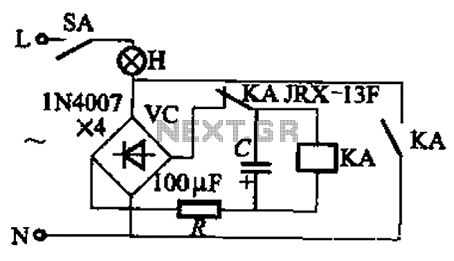
The circuit illustrated in Figure 13-3 consists of two configurations: (a) a DC power supply and (b) an AC power supply. Both configurations are utilized to control a relay. The flash frequency of the relay is determined by the...
For the simplest functions, such as a flashing indicator and/or beeper, a printed circuit board is not necessary. Components can be directly soldered onto the legs of the PIC microcontroller, using heat-shrinkable sleeves for insulation. Caution is advised to...