
1000:1 Tuning Voltage-Controlled Filter

The dual integrator filter is a versatile circuit commonly used in audio signal processing, particularly in synthesizers and electronic music applications. The core of the design relies on the CA3080 operational amplifier, known for its ability to function as a current-controlled integrator. The integration process allows for the shaping of frequency responses, which is essential in sound synthesis.
The configuration begins with three CA3080s at IC1, where they operate as current-controlled integrators. The current control enables the adjustment of the integration rate, directly influencing the filter's response characteristics. The resonant frequency, determined by the values of L, A, B, and C, can be finely tuned to sweep across a broad spectrum, allowing for creative sound design.
At IC2, four additional CA3080s are configured as voltage followers. This configuration is crucial as it buffers the outputs from the high-impedance integrators, ensuring that the signal integrity is maintained while providing a low-impedance output suitable for interfacing with other circuit elements or external devices.
The third CA3080 (IC5) plays a pivotal role in controlling the Q factor, which is a measure of the selectivity or sharpness of the filter's resonance. A higher Q factor results in a narrower bandwidth around the resonant frequency, producing a more pronounced peak in the frequency response, which is desirable for creating distinctive tones in electronic music.
The dual integrator filter produces two primary outputs: a low-pass response that allows frequencies below a certain threshold to pass while attenuating higher frequencies, and a bandpass response that selectively allows a specific range of frequencies to pass through. This dual functionality enhances the versatility of the filter, making it suitable for various applications in sound synthesis and audio processing. The ability to manipulate the resonant frequency and Q factor offers musicians and sound designers a powerful tool for creating unique audio effects and textures. A standard dual integrator filter can be constructed using a few CA3080s. By varying LABC, the reso nant frequency can be swept over a 1000:1 range. At IC1, three are current-controlled integrators. At IC2, four are voltage followers that serve to buffer the high-impedance outputs of the integrators. A third CA3080 (IC5) is used to control the Q factor of the filter. The resonant frequency of the filter is linearly proportional to /abc· Hence, this unit is very useful in producing electronic music.
Two outputs are produced: a low-pass and a bandpass response.
Related Circuits
A simple passive circuit is designed to match an antenna to a radio receiver without requiring any power. This circuit is beneficial for shortwave listeners and can also utilize a medium wave coil to tune into the medium wave...
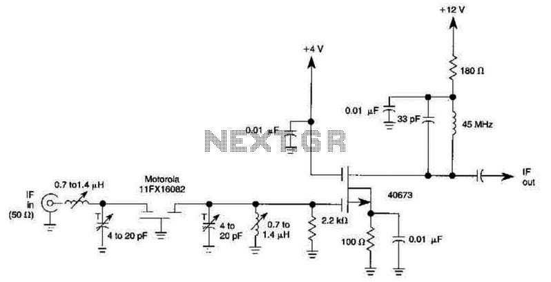
A 40673 dual-gate MOSFET is matched to a crystal filter operating at 45 MHz. The filter impedance is approximately 2 kΩ. The +4 V source can be adjusted to control the gain, ranging from +4 V to -4 V. The...
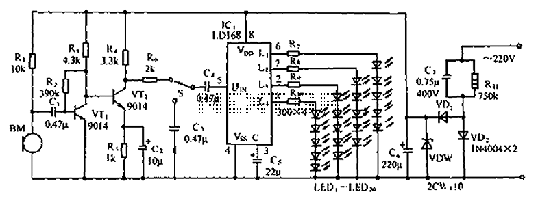
The circuit depicted in the figure involves the LD168, which functions as a sound level indicator for tape recorder speakers. It features four outputs capable of directly driving multiple light-emitting diodes. Additionally, the device can be activated by a...
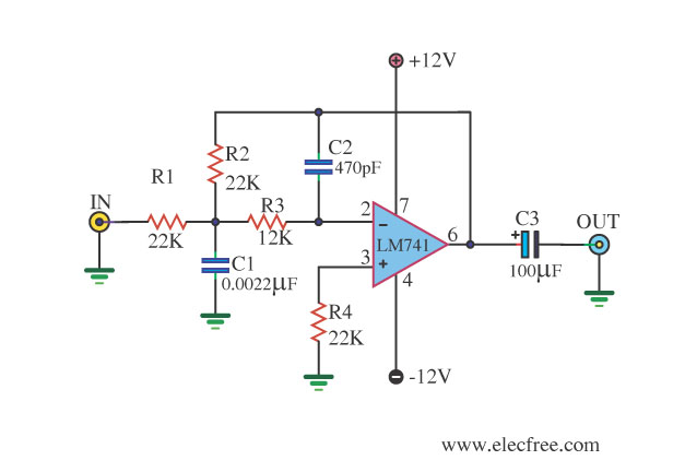
This circuit filters low frequencies below 10 kHz using the highly popular operational amplifier IC uA741. It is convenient for applications that require the conversion of analog signals to digital or vice versa. In digital sound systems, this circuit...
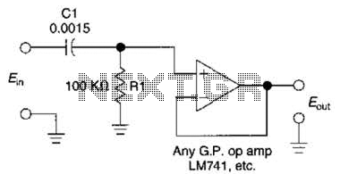
This simple 1 kHz filter utilizes a voltage follower and an RC section as its filtering element. For other frequencies, the -3 dB point is given by the formula 1/(6.28 Rl Cv), and the response decreases at a rate...
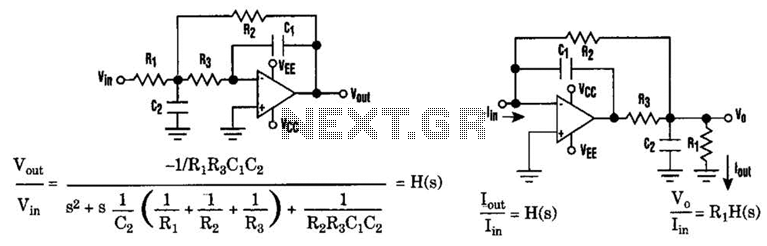
The low-pass Sallen-Key filter is a staple for designers because it contains few components. By redesigning the filter, a current-to-voltage conversion can be avoided when the input signal to be filtered is in current form. The Sallen-Key filter is a...