
DIY IRF610 MOSFET Class-A Headphone Amplifier Project

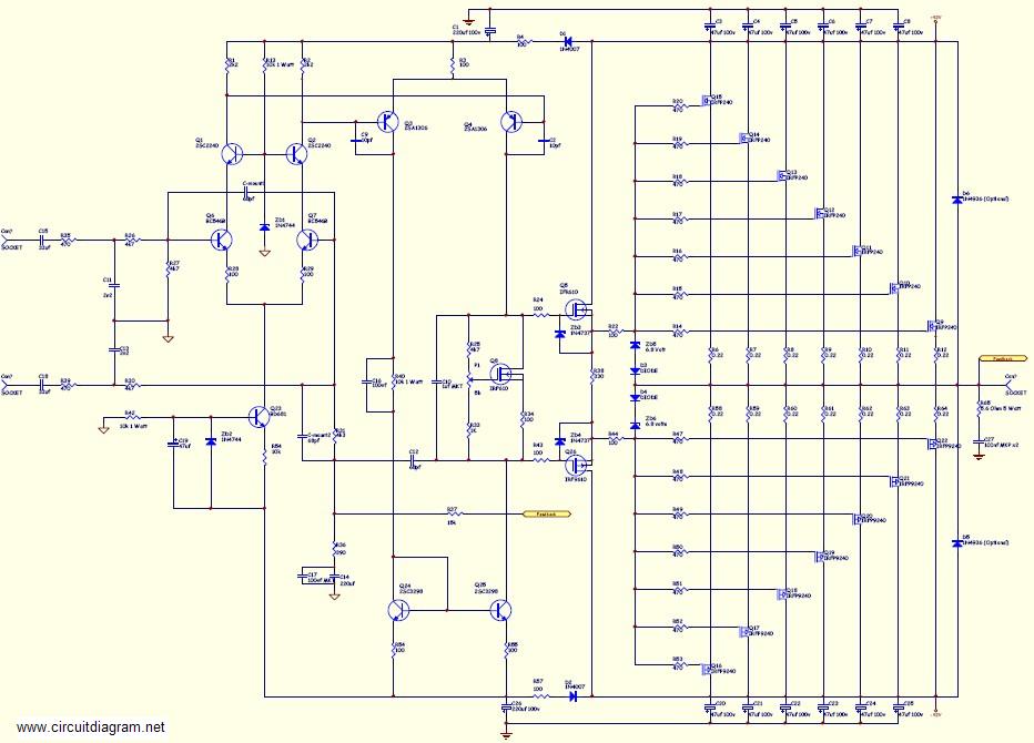
It is important to note that a FET follower circuit can supply high current but has a voltage gain of less than one. Thus, this amplifier is suitable only for applications without voltage amplification requirements. Additionally, a simple single-ended circuit lacks power supply ripple rejection, allowing any noise from the power supply to pass through the amplifier. Consequently, a regulated power supply is necessary; suitable inexpensive options can be acquired from Radio Shack, with specifications of 10-20VDC and 750mA being adequate. The schematic for this headphone amplifier is illustrated in Figure 2. An IRF610 MOSFET is utilized, although various FET devices, such as the IRF510, IRF611, IRF612, and IRF710, can also be employed. It is advisable to avoid using IRF530 or IRF540 types, as they tend to exhibit poor high-frequency performance.
The design incorporates a common LM317 voltage regulator configured as a precise CCS, set to draw 250mA. Given that this headphone amplifier is intended for use on a desk, it is designed to fit seamlessly into an office environment. An old Plextor external CD-ROM case was repurposed as the enclosure, which conveniently included a power switch, power adapter receptacle, RCA inputs, and a headphone jack. The amplifier is built on approximately 1.75-inch square protoboards from Radio Shack, although any suitable board may be used. Standard components were utilized, including matched metal film resistors, a 1µF mylar input capacitor, and a 0.47µF polypropylene bypass capacitor on the output, along with a 0.1µF decoupling capacitor, also polypropylene. While some may opt for higher quality input and bypass capacitors for improved sound, the use of metal film resistors is recommended, particularly for the CCS, due to their superior temperature stability compared to carbon resistors. Heat sinks salvaged from various discarded components were employed; the smaller heat sinks measure approximately 1.75 inches square and remain moderately warm, aided by the metal chassis for heat dissipation. Proper isolation of the MOSFET and regulator from the heat sinks is essential. Initial testing of the headphone amplifier was performed using a regulated power supply at a low voltage to ensure functionality. The bias is adjusted by varying a 100k variable resistor until the output side of the MOSFET (source) reaches half of the supply voltage.
This comprehensive approach ensures that the headphone amplifier meets the demands of both performance and usability in an office environment while being built from readily available components.Not thrilled with how a computer soundcard drove my 32 ohm Grado SR80 headphones, I decided to build myself a desktop headphone amplifier for the office. In this instance I had plenty of voltage gain, but the sound card just runs out of gas with good headphones.
This amplifier will only be suitable in setups where the input signal does not require voltage amplification (such as the output of a preamplifier, mp3 player or computer). This amplifier will delivery plenty of current to drive more demainding headphone types. This is a simple do-it-yourself (DIY) headphone amplifier project that is fashioned primarily after the Class-A MOSFET Headphone Driver project by Greg Szekeres and to some extent Mark`s DIY Class-A 2SK1058 MOSFET Amplifier Project. The amplifier concept is simple and follows a typical single-ended class-A circuit utilizing an active constant current source (CCS) in place of a passive resistor.
A CCS doubles the efficiency of the circuit over that where a passive load resistor is used, bringing it to a maximum of 25%. There are a couple of items to note. A FET follower circuit will be able to supply high current, but the voltage gain will be less than one.
This amplifier will only be suitable in applications where the input signal does not require voltage amplification (such as the output of an mp3 player or computer). Also, a simple single-ended circuit like this will have no power supply ripple rejection and thus any noise in the power supply is going to go right through amplifier.
For that reason, you will need to use a regulated power supply. Suitable inexpensive regulated (wall wart) power supplies can be purchased from Radio Shack. 10-20VDC and 750mA should be fine. The schematic for this headphone amplifier project is shown below in Figure 2. An IRF610 MOSFET is used in this example, but a wide variety of FET devices can be used in its place. I`ve had success with IRF510, IRF610, IRF611, IRF612 and IRF710, all of which worked well. You will want to stay away from IRF530 or IRF540 types (commonly found in power supplies) as there will be terrible roll-off of the highs.
Using a simple application of a common LM317 voltage regulator it is configured as a very accurate CCS set to draw 250mA. This headphone amplifier will reside primarily on my desk at work, so it needs to fit into an office environment.
Fortunately I had a dead Plextor external CD-ROM kicking around that would make for the perfect enclosure and blend in well on my desk. Even better yet, it already had a power switch, power adapter receptacle and RCA inputs on the back as well as a headphone jack on the front.
Perfect! The open hole you see on the back is where the USB header resided, but I had previously salvaged that for another project. The amplifier is constructed on ~1. 75" square protoboards from Radio Shack (276-148), but any board will work. I only used parts that I had on hand and you can see that I did not use any boutique parts. Plain (but matched) metal film resistors, 1uF mylar input cap and 0. 47uF polypropylene bypass cap on the output. The 0. 1uF decoupling capacitor is also polypropylene. Some may prefer to use higher quality input and bypass caps and that should improve the sound. You can use carbon resistors, but I suggest you use metal film, particularly for the CCS due to their superior temperature stability over carbon.
The heat sinks were salvaged from various dead components. The smaller heat sinks are about 1. 75" square and only get moderately warm, but keep in mind that the heat sinks are attached to the metal chassis which also helps dissipate some heat. Be sure to isolate the MOSFET and regulator from the heat sinks. The headphone amplifier was first tested (smoke test) using a regulated power supply at very low voltage.
The bias is set by varying the 100k variable resistor until the output side of the MOSFET (Source) is at one-half of the supply volta 🔗 External reference
Related Circuits
This amplifier is suitable for various applications that demand high power, low noise, minimal distortion, and superior sound quality. Examples include subwoofer amplifiers, front-of-house (FOH) stage amplifiers, and individual channels of high-powered surround sound amplifiers. For a detailed explanation...
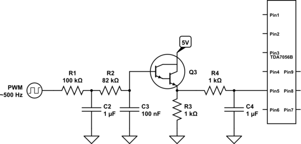
A voltage between 0.4 and 1.2 V is required on pin 5 to control the gain. In the initial two versions of the circuit, logic ICs and/or counters were utilized along with an operational amplifier and a resistor network...
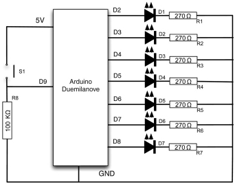
Electronic devices require precision. When a task is performed multiple times, the outcome is consistently the same. However, there are instances where random results are desirable, such as in gaming applications. This project demonstrates how to create a lottery...
The XLR connector facilitates the connection of the microphone's output to the preamplifier circuit. This preamplifier was designed and constructed by Electrical Engineers using discrete components. The signal from the preamplifier is subsequently fed to the Maxim Class-D amplifier....
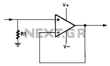
An operational amplifier (op amp) can function as a unity gain amplifier by connecting its output to its inverting input as illustrated. The load resistance (Rl) should be sufficiently low to prevent the op amp's bias current from introducing...
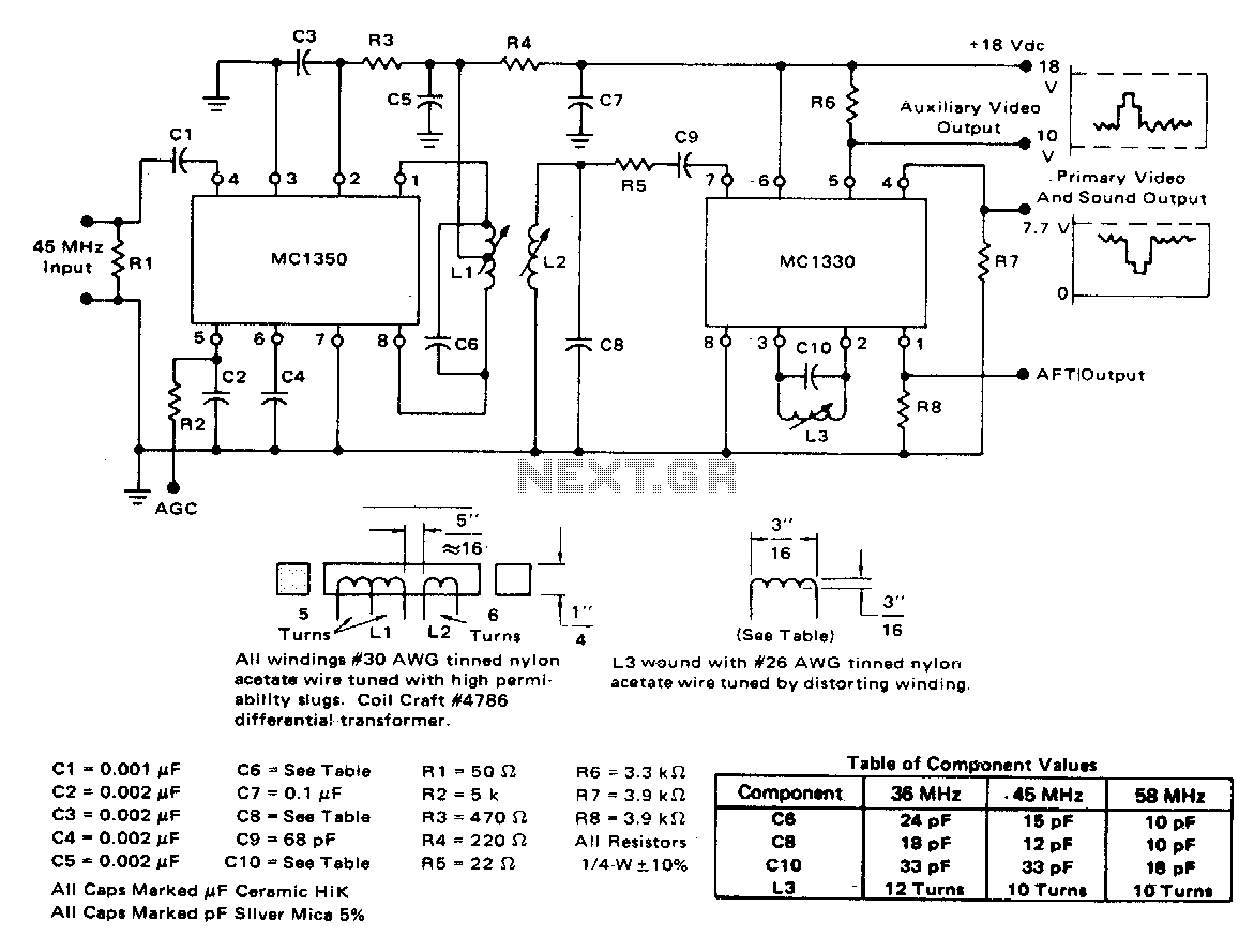
The circuit exhibits a typical voltage gain of 84 dB and an automatic gain control (AGC) range of 80 dB. It demonstrates minimal alterations in bandpass shape, generally less than 1 dB tilt for 60 dB compression. There are...