
diy opto-isolated power switch

An opto-isolated power switch is an essential component in many electronic systems, particularly when interfacing low-voltage control circuits with high-voltage or high-current loads. The primary purpose of this switch is to provide electrical isolation between the control circuit and the load, thereby protecting sensitive components from high voltage spikes and noise.
The circuit typically consists of an opto-isolator, a power transistor or relay, and necessary supporting components such as resistors and capacitors. The opto-isolator, also known as an optocoupler, contains an LED and a phototransistor. When a logic-level signal is applied to the LED, it emits light, which is detected by the phototransistor. This action allows the phototransistor to conduct, thus enabling current to flow through the load circuit.
For heavy loads, a power transistor (such as a MOSFET or BJT) or a relay can be used as the switching element. The choice between a transistor and a relay depends on the specific application requirements, including the load type, switching speed, and isolation needs. A relay provides complete electrical isolation and is suitable for AC loads, while a power transistor offers faster switching speeds and is ideal for DC applications.
Supporting components play a critical role in ensuring the reliability and efficiency of the circuit. A current-limiting resistor is often placed in series with the LED of the opto-isolator to prevent excessive current flow. Additionally, a pull-down resistor may be required on the output side to ensure the transistor remains off when no signal is present. Capacitors can be added for noise filtering and to stabilize the circuit operation.
When designing the circuit, careful consideration must be given to the voltage and current ratings of all components, ensuring they can handle the maximum load conditions. Proper heat dissipation methods, such as heat sinks for transistors, should also be implemented to prevent thermal failure.
Overall, the opto-isolated power switch is a vital solution for safely controlling heavy loads with low-voltage logic signals, making it widely applicable in industrial automation, home automation systems, and various electronic projects.This article describes how to build an opto-isolated power switch for controlling heavy loads with logic levels.. 🔗 External reference
Related Circuits
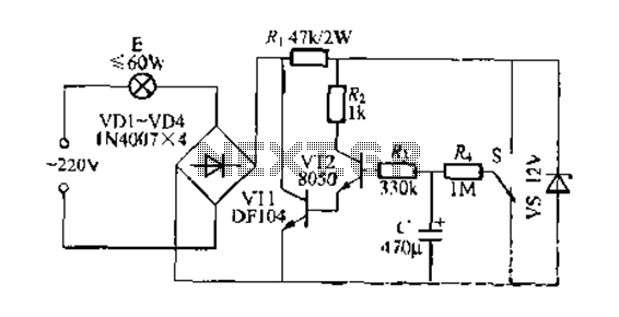
This circuit is a gradual clear/fade switch for a two-wire connection, designed for simple installation. It activates the lights as needed by turning the switch dial upward. A positive supply of 2V is provided through resistor R. The capacitor...
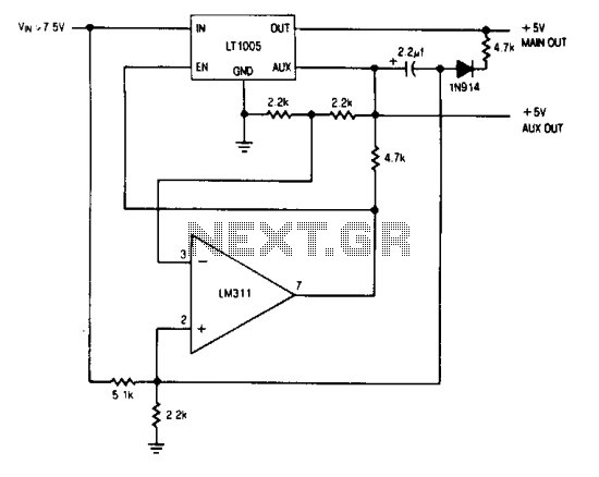
The auxiliary output powers the memory, while the main output powers the system and is connected to the memory store pin. When power goes down, the main output goes low, commanding the memory to store. The auxiliary output then...
The heart rate measurement project utilizing fingertip photoplethysmography was constructed using salvaged components, specifically an infrared LED and a photodiode. Due to the nature of these parts, their specifications could not be provided in the article. The heart rate measurement...
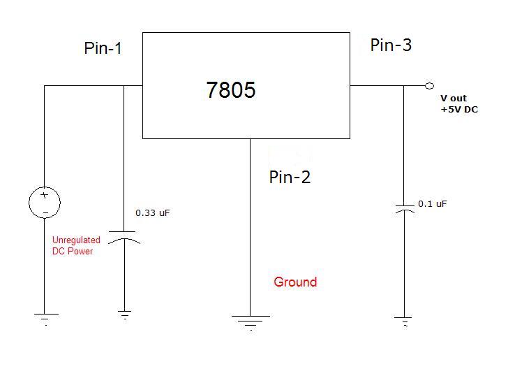
Many different devices require DC power and thus need an I.T.E power supply. I.T.E stands for "Information Technology Equipment." An example of such a device is an iPod speaker system that is no longer functional, which originally came with...
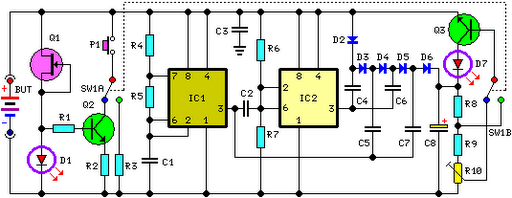
FET Q1 functions as a constant current generator, providing biasing for LED D1 and the base of Q2. This configuration ensures that D1 emits light at a consistent intensity, regardless of the battery voltage, which ranges from 3 to...
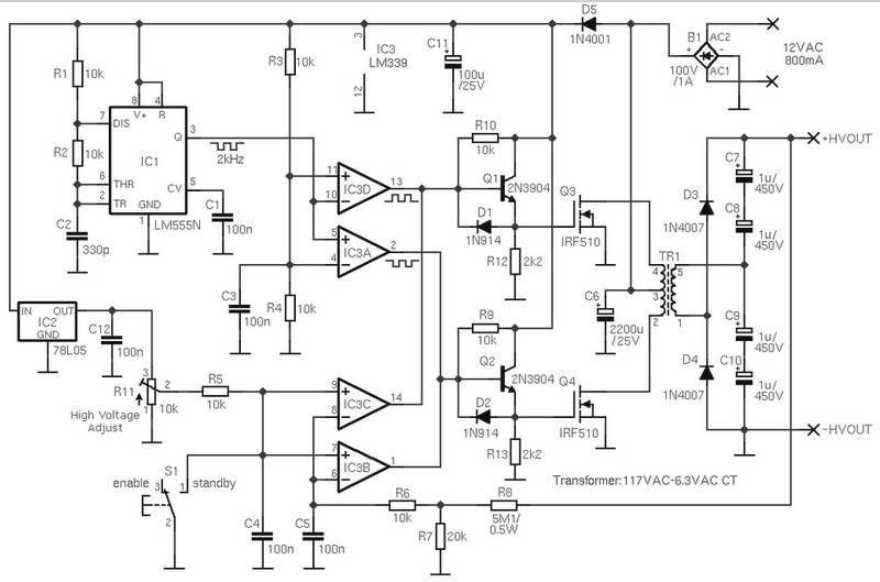
The schematic diagram is derived from the circuit for an Adjustable High Voltage Power Supply, which can output voltages ranging from 0 to 1000V. A suitable source of alternating voltage for the high voltage converter is 12V / 800mA....