Easy Pulse: A DIY photoplethysmographic sensor for measuring heart rate. Part 1 - Theory and Schemat
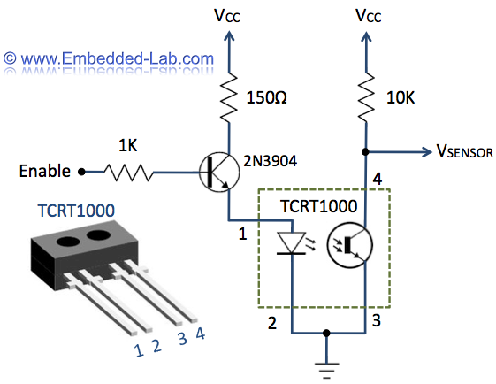
The heart rate measurement project utilizing fingertip photoplethysmography was constructed using salvaged components, specifically an infrared LED and a photodiode. Due to the nature of these parts, their specifications could not be provided in the article.
The heart rate measurement system based on fingertip photoplethysmography operates by analyzing blood volume changes in the fingertip, which are detected through light absorption characteristics. The core components of this system include an infrared LED, which emits light that penetrates the skin, and a photodiode, which senses the light that is reflected back.
In this project, the infrared LED emits light at a wavelength typically around 940 nm, which is optimal for penetrating human tissue and minimizing interference from ambient light. The photodiode is positioned to receive the light that is reflected from the fingertip, where variations in blood volume during each heartbeat alter the amount of light absorbed versus reflected.
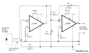
The circuit design includes a current-limiting resistor in series with the infrared LED to prevent excessive current flow, ensuring the longevity of the component. The photodiode is connected to an operational amplifier configured as a transimpedance amplifier, which converts the small current generated by the photodiode into a measurable voltage signal. This voltage signal is then processed by a microcontroller or an analog-to-digital converter (ADC) to calculate the heart rate.
To enhance the accuracy of the measurements, additional circuit elements such as filters may be implemented to reduce noise and improve the signal-to-noise ratio. A low-pass filter can be used to smooth out high-frequency noise, while a high-pass filter may help eliminate baseline wander caused by motion artifacts.
Overall, the heart rate measurement circuit is a practical application of photoplethysmography, showcasing how salvaged components can be effectively utilized to create a functional health monitoring device.When I first built the Heart rate measurement through fingertip project, the infrared LED and photodiode used for finger photoplethysmography were actually from salvaged parts, and therefore, I could not provide specifications for them in the article. As a result of that it takes quite a bit of. 🔗 External reference
