
DIY Tremolo Effect

This tremolo effect circuit is designed to provide a versatile modulation effect suitable for audio applications, particularly in stereo setups. The XR2206 function generator is central to generating the modulation waveforms, specifically the sine wave, which is essential for achieving the desired audio effects. The modulation frequency, adjustable via P1, allows for fine-tuning of the tremolo effect, accommodating various musical styles and preferences.
The resistors R5 and R6 play a critical role in defining the output characteristics, specifically influencing the amplitude and DC offset of the modulation signal. Capacitor C2 serves to smooth out any ripple in the output, ensuring a clean signal is fed into the subsequent stages of the circuit. The combination of the square wave output and the LED indicator provides visual feedback, allowing users to monitor the modulation frequency easily.
The TCA730 IC, known for its volume control capabilities, is effectively utilized here, with pin 13 receiving the modulating voltage to create a dynamic volume modulation effect. This integration allows for the simulation of the Lesley effect, where the sound appears to swirl and move, reminiscent of a rotating speaker cabinet. The adjustment of P2 provides further control over the intensity of this effect, enabling users to customize their sound.
Finally, the recommendation for a regulated power supply, such as the 7815 IC, underscores the importance of stable voltage in audio circuits. Variations in power supply can lead to inconsistent modulation results, which would detract from the overall performance of the tremolo effect circuit. This design emphasizes the importance of careful component selection and configuration to achieve a professional-quality audio effect.This tremolo effect circuit uses the XR2206 and the TCA730 IC which is designed as an electronic balance and volume regulator with frequency correction. The circuit is use full for stereo channels and it also has the ability to simulate the Lesley effect aka rotating loudspeaker effect.
Balance and volume settings are done with a linear potentiome ter for both channels. If this potentiometer is replaced with an AC voltage source, a periodic modulation of the input signal can be achieved. This AC voltage source comes from the function generator IC XR2206. This IC generates square, triangle and sine wave signals but for this project we use only the sine wave.
The modulation voltage can be varied with P1 from 1 Hz up to 25 Hz. Resistor R3 sets the operation level of the sine wave generator. R5 and R6 set the DC voltage and the sine wave amplitude at the output. C2 is a ripple filter. The square wave output of the XR2206 drives T2 and a LED to optically display the frequency. The modulating voltage reaches pin 13 of TCA730 via P3 and R10. This input functions as the volume control or in this case the volume modulation. The degree of the balance modulation (Lesley effect) can be varied with P2. A regulated power supply using 7815 IC is recommended. Do not use a non-stabilized power supply since the current variations would influence the modulation negatively. 🔗 External reference
Related Circuits
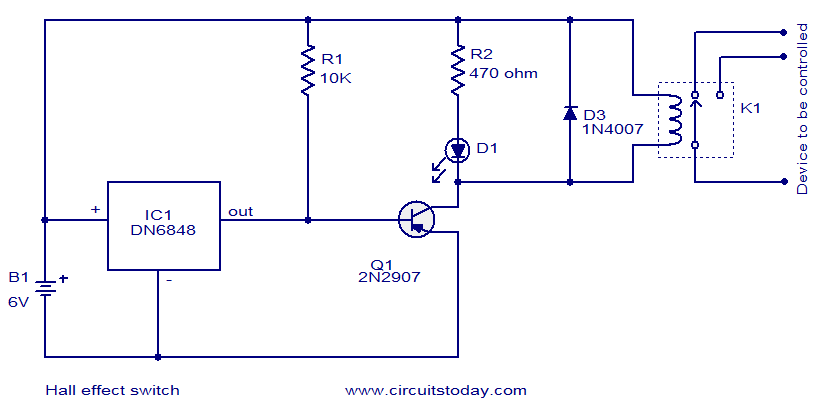
The circuit diagram presented is for a Hall Effect switch. The core component of this circuit is the Hall Effect sensor IC DN6848 from Panasonic. This integrated circuit features a Hall Effect sensor, a Schmitt trigger circuit, a power...
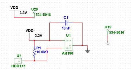
The chosen Hall Effect sensor is the AH180 Micropower Omnipolar Hall-Effect Sensor Switch. This sensor is utilized to detect the removal of a cup. The operational principle of the Hall Effect sensor involves outputting a high or low signal...
Make your own Guitar Effects Pedal with an Arduino board. Bit crushing, rate reducing, weird noises. 10-bit effects/guitar pedal with an Arduino for lo-fi DSP The project involves designing a guitar effects pedal utilizing an Arduino microcontroller to create various...
An infrared illuminator can be constructed at home with minimal effort, requiring only basic knowledge of electronics. The circuit is straightforward, utilizing 68 Ohm, 1 Watt resistors. Infrared LEDs are readily available at most electronics stores. Users have reported...
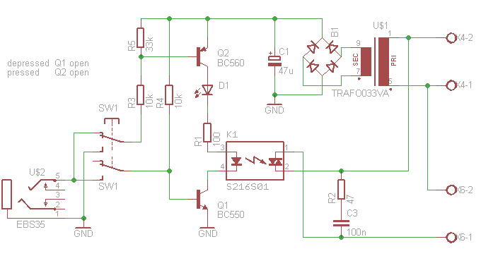
This article outlines the construction of an opto-isolated power switch designed for controlling heavy loads using logic-level signals. An opto-isolated power switch is an essential component in many electronic systems, particularly when interfacing low-voltage control circuits with high-voltage or high-current...
The LA1061M is an antenna switching controller designed for mobile radio equipment. It utilizes several inputs from the receiver circuitry to choose between the main antenna and a sub-antenna based on signal strength and quality. Weak and strong signals...