
DIY Tremolo Effect

This tremolo effect circuit offers a versatile platform for audio modulation, combining advanced components to create a rich sound experience. The XR2206 serves as the heart of the modulation process, generating precise sine wave signals that are crucial for achieving the desired tremolo effect. The choice of using a linear potentiometer allows for smooth adjustments in both balance and volume, facilitating user-friendly operation.
The integration of the TCA730 enhances the circuit's capability by providing effective volume control, allowing for dynamic sound modulation. The modulation range of 1 Hz to 25 Hz, adjustable via potentiometer P1, enables a wide variety of tremolo effects, making this circuit suitable for different musical styles. The ripple filter (C2) ensures that the output remains clean and free from unwanted noise, which is essential for maintaining audio fidelity.
The visual feedback provided by the LED connected to T2 is a valuable feature, allowing users to monitor the modulation frequency in real-time. This can be particularly beneficial in live performance settings, where quick adjustments may be necessary.
Overall, this tremolo effect circuit is designed for reliability and performance, with careful consideration given to power supply stability. The recommendation to use a regulated power supply with the 7815 IC ensures that the circuit operates consistently, preventing modulation issues that could arise from voltage fluctuations. The inclusion of a heat sink for the 7815 further enhances the circuit's durability, allowing it to handle extended use without overheating.This tremolo effect circuit uses the XR2206 and the TCA730 IC which is designed as an electronic balance and volume regulator with frequency correction. The circuit is use full for stereo channels and it also has the ability to simulate the Lesley effect aka rotating loudspeaker effect.
How does the tremolo effect circuit works Balance and volume settings are done with a linear potentiometer for both channels. If this potentiometer is replaced with an AC voltage source, a periodic modulation of the input signal can be achieved. This AC voltage source comes from the function generator IC XR2206. This IC generates square, triangle and sine wave signals but for this project we use only the sine wave.
The modulation voltage can be varied with P1 from 1 Hz up to 25 Hz. Resistor R3 sets the operation level of the sine wave generator. R5 and R6 set the DC voltage and the sine wave amplitude at the output. C2 is a ripple filter. The square wave output of the XR2206 drives T2 and a LED to optically display the frequency. The modulating voltage reaches pin 13 of TCA730 via P3 and R10. This input functions as the volume control or in this case the volume modulation. The degree of the balance modulation (Lesley effect) can be varied with P2. A regulated power supply using 7815 IC is recommended. Do not use a non-stabilized power supply since the current variations would influence the modulation negatively. Attach the 7815 IC to a good heat sink (about 10 cm2). 🔗 External reference
Related Circuits

The TNT Convertus is a notable design that has gained significant attention as one of the first DIY DAC projects published in Italy. Although several modifications have been made to the original Convertus design, time constraints have prevented further...
This tremolo effect circuit utilizes the XR2206 and TCA730 integrated circuits (ICs), designed for electronic balancing and volume regulation with frequency correction. The circuit is suitable for stereo channels and can simulate the Lesley effect, also known as the...
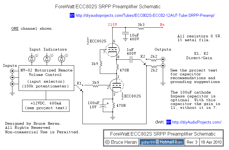
The project involves a shunt-regulated push-pull (SRPP) driver stage. Research and modeling have been conducted on the SRPP, highlighting its advantages, which include good linearity, low distortion, low output impedance, effective power supply noise rejection, and moderate gain. The...
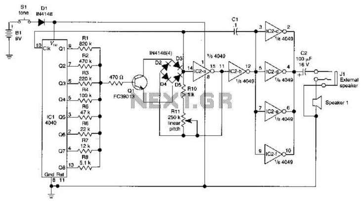
The circuit comprises four main components: a binary counter, a digital-to-analog (D/A) converter, a voltage-controlled oscillator (VCO), and an audio output amplifier. The counting speed of the binary counter is influenced by the frequency output from the VCO, which...
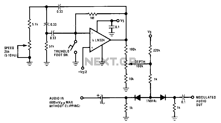
A phase shift oscillator utilizing the LM324 operates at an adjustable frequency range of 5-10 Hz, which is determined by a speed potentiometer. A segment of the oscillator output is extracted from the depth potentiometer and is employed to...
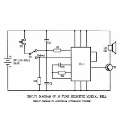
The core of the circuit is an IC4822, referred to as IC1. The IC4822 is a programmed ROM that produces 16 musical tunes upon being triggered. Its main features include an integrated tone generator, rhythm generator, modulator, oscillator, frequency...