
door alarm

There is uncertainty regarding the construction of a momentary reed switch. A previous switch was disassembled, but it is unclear if the current switch can be modified. It is suggested that the metal strip inside could be bent to convert it to a normally closed configuration. A magnet from a small speaker has been repurposed, and a concept is presented where a thin metal strip across two screws would short them together. When the magnet attached to the door approaches, one end of the metal strip would lift off one screw, breaking the circuit. The effectiveness of this custom-made normally closed switch depends on the correct bending of the metal.
An inverter is described as a basic digital integrated circuit that inverts the input signal, making it resemble a normally closed switch. The suitability of the inverter depends on the voltage levels and current requirements of the application, as inverters typically handle lower currents compared to switches. The switch is designed to operate with 9 to 12 volts, activating a two-tone siren circuit built with two NE555 timer ICs. A relay can be added for a normally open configuration, although it may complicate the switch mechanism design.
The siren circuit includes a delay timer set for 30 seconds, utilizing two additional relays—one for arming the siren and another to maintain the siren's operation even after the door is closed. The circuit was initially tested with a 9-volt power supply, but a 12-volt supply damaged the 555 timer IC and the transistor in the delay timer circuit, despite all components being rated for 16 volts or higher. The circuit has been repaired and will continue to operate at 9 volts.
The schematic includes a key switch that both arms the alarm and initiates the delay timer circuit by grounding pin 2 of the 555 IC, which activates a resistor (R2) that prevents the siren from sounding. Once the door opens, another resistor (R3) maintains the circuit around the door switch. A keypad is employed to start a 3-second latch timer pulse for arming or disarming the alarm, with the key switch located outside the door. An LED above the key switch indicates that the delay timer is active, providing time to enter the code. The keypad is used for arming the alarm from inside and disarming it with a key code.
The circuit design emphasizes reliability and functionality, ensuring that the alarm system is effective in securing the area while providing a user-friendly interface for operation. Proper voltage levels and component ratings are critical for the circuit's longevity and performance, and careful attention to the design of the switch mechanism will enhance the overall effectiveness of the alarm system.Another way other than magnetic reed switches for the alarm trip switch. The circuit needs the switch to be normally closed / held open (when the door is shut. ). I was looking to use a normally closed momentary push button. Another thought was trying to make a DIY magnetic switch myself. Are there any ideas that anyone else has to make a passive door alarm switch You could feed your circuit from an inverter. I`m not sure how you would go about making a momentary reed switch. The last switch I had was just like yours, it was disassemble though not sure if yours is. You could probably covert it to a NC if you bend the metal strip inside just right. I pulled a magnet from a tiny speaker. I was thinking that a thin strip of metal lying accross a two screws attached at one end shorting them together. When the magnet (on the door) gets close one end of the metal strip would lift off one of the screws breaking the circuit.
I`m not sure if I can get that to work though. Your custom made NC switch should work if you can get the metal bent just right. An inverter is a very basic digital IC. If you input a high voltage it outputs low and vice versa, so it will invert the signal coming from your switch, making it look like a NC switch. Depends on what voltages you`re running at and what you`re switching because inverters don`t generally pass as much current as a switch can, if it`s just a signal though it would work fine.
The switch makes or brakes 9 to 12 volts feeding a two tone siren circuit I made using two NE555 timer IC`s. (UK siren) I can use another relay if I want the switch to be normally open but I don`t think that makes the switch mechanizm design any easier to accomplish.
The first is the siren circuit I used and the other is the delay to enter timer circuit, set for 30 seconds. I`ve added two more relays to the circuit. One is a latch for arming the siren circuit and the other seals around the door switch so the siren continues to sound even after the door is closed.
Originally I stated that the circuit could handle from 9 to 12 volts. Well I was using a 9 volt power supply. When I tried a 12 volt supply it fried the 555 timer IC and the transister in the delay to enter circuit. I`m not sure why. All the componants were rated at 16 volts or higher. I fixed it and will stay with 9 volts. Pics of it will be posted soon. I know this a crude drawing but this is the circuit I used. Keep in mind that the key switch (momentary) both arms the alarm and starts the delay timer circuit by grounding pin 2 of the 555 IC (delay to enter timer) this turns on R2 blocking the siren from sounding.
Keep in mind that R2 is actually in the delay timer circuit in the schematic. After the door opens R3 seals on around the door switch. The keypad starts a 3 second latch timer pulse to either arm or disarm the alarm (R1). The key switch is mounted outside the door and is used when leaving or entering the door it has a green LED above the key switch to show the delay timer is timing giving me time to enter and type the code in. The keypad is used to arm the alarm from the inside and to disarm the alarm with the key code. 🔗 External reference
Related Circuits
The operation of a 303MHz circuit has been covered in our project WIRELESS DOORBELL. We are not going over how the circuit works but explain the importance of some of the components and how they affect the range. The...
It is a significant advantage that most modern vehicles are equipped with built-in alarm systems. However, the sound of the horn when the alarm is armed can be perceived as noise pollution. Disconnecting the alarm system from the horn...
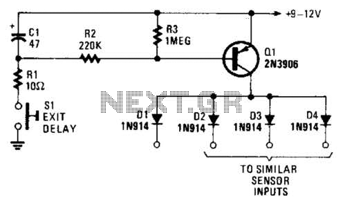
Depressing SI charges CI to the supply voltage. This biases Q1 on via bias resistors R2 and R3. A voltage is available for the duration of the delay period to hold off the alarm circuit. CI can be increased...
The doorbell button was replaced with a lighted version, but the chime continued to sound after the button was pressed. These lighted buttons incorporate an incandescent bulb in parallel with the button, a component that has been modified in...
The device described here does just that. The circuit connects to the doorbell circuit, taking power from the 18 VAC from the doorbell transformer and switching power to the doorbell circuit most of the day. The user interface is...

This circuit schematic produces a beep and/or illuminates an LED when someone touches the door handle from outside. The alarm will continue to sound until the circuit is switched off. The circuit operates on the principle of capacitive sensing, where...