
Door chimes delay

This circuit functions as a basic timer using a capacitor and resistor in a charging configuration. When the button is pressed, it initiates the operation, and upon release, the capacitor C1 begins to charge through the resistor R1. The time it takes for the capacitor to charge to a certain voltage level determines the delay before the next operation can occur. The time constant of the circuit, which is the product of the resistance (R1) and the capacitance (C1), dictates the charging time.
The relationship between the resistance and the delay is linear; thus, increasing the resistance value of R1 will proportionally increase the time it takes for the capacitor to reach the threshold voltage required to trigger the circuit's next operation. This can be useful in applications where a precise timing interval is necessary, such as in timers, delay circuits, or pulse generators.
In practical applications, selecting the appropriate values for R1 and C1 is crucial to achieving the desired delay. For instance, if a longer delay is required, a larger resistor or capacitor can be selected. Conversely, for shorter delays, smaller values should be chosen. Additionally, it is important to consider the voltage rating of the capacitor to ensure it can handle the charged voltage without failure.
Proper circuit layout and component selection will ensure reliable operation and longevity of the circuit. The simplicity of this design makes it an excellent choice for educational purposes, as well as for use in basic electronic projects where timing control is needed.With values shown, this simple circuit will permit one operation every 10 seconds or so. Capacitor C1 charges through Rl when the button is released Making Rl larger will increase the delay.
Related Circuits

This project involves an electronic lock that supports numerous combinations, which can be easily modified. It unlocks only with the correct sequence of four consecutive numbers. A significant feature of this electronic lock is that the four numbers must...

This is a circuit design for a doorbell that produces a bird-like sound. The circuit is controlled by an NPN transistor. The operation of the circuit begins when P1 is set to an experimental value, starting with approximately 220...
This circuit provides a delayed visual indication when a doorbell switch is pressed. Additionally, a double pole double throw (DPDT) switch can be activated from within the house to light a lamp at the doorbell switch. The lamp can...
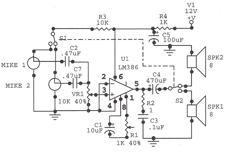
The LM386 is an ideal choice for a door phone application. This device is particularly beneficial in modern urban households, utilizing a condenser microphone and a speaker. The LM386 is a low-voltage audio power amplifier that is commonly used in...
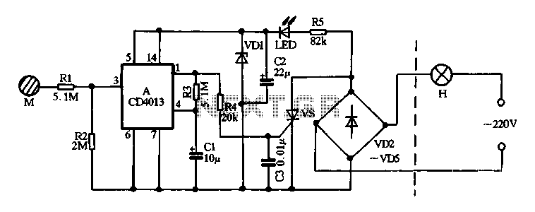
Diodes VD2 to VD5 and SCR form the main circuit of a touch switch. Resistor R5 and diode VD1 create a power supply circuit that outputs approximately 12V DC, which is utilized for a manifold A application. The circuit...

This Outdoor LED Solar Garden Lights project is a hobby circuit for an automatic garden light that utilizes a light-dependent resistor (LDR) and a 6V/5W solar panel. During daytime, the internal rechargeable 6 Volt sealed lead-acid (SLA) battery is...