
Door electronic lock with Keypad
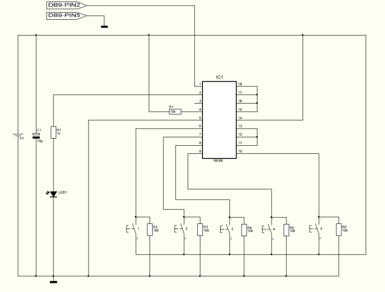
The electronic lock circuit described is a 7-digit code-based locking mechanism that utilizes a series of components to ensure secure access control. The core of the circuit is the integrated circuit IC1, which is a 4022 decade counter. This IC is responsible for counting the input signals from the push-button switches (S1-S10) that represent the digits of the code. Each switch corresponds to a specific digit, and the sequence must be entered correctly without any delays for the system to recognize the input.
The circuit employs a series of resistors (R1-R14) and capacitors (C1-C3, C2) to manage the timing and signal integrity. The resistors R1-R7, for instance, are configured to provide pull-up or pull-down functionality, ensuring that the inputs to the IC are stable during operation. R12, a 220 kOhm resistor, is likely used to limit current and protect the IC from overcurrent conditions.
When the correct sequence of keys is pressed, the output Q7 of the IC is activated for approximately 4 seconds. This output drives the transistor Q2 (BD679), which can control a relay that ultimately opens a door or activates another circuit. The relay provides the necessary isolation and power handling capability to control larger loads that the circuit might need to operate.
Additionally, the circuit includes a visual indicator in the form of a red LED (D3), which illuminates when the lock is activated, providing an optical clue of the system's status. The diodes D1 and D2 (1N4148) are used for flyback protection across the relay to prevent voltage spikes when the relay is de-energized.
The flexibility of the circuit is highlighted by the ability to change the code. By altering the connections between the outputs of IC1 and the switches, a different 7-digit code can be implemented without significant redesign. This adaptability is crucial for maintaining security, as it allows users to modify access codes periodically.
Overall, this electronic lock circuit represents a robust and straightforward solution for secure entry systems, combining basic electronic components to create a reliable locking mechanism.It is a relatively simple circuit of electronic lock of safety with code of 7 digits. It should is given attention in the time that will be stepped the keys, that shape code and it does not exist it delays. With the right step of keys and if code is right then is activated exit Q7 for roughly 4 seconds, driving the transistor Q2, which with the line can drive one relay, for the opening of door, or any other circuit.
With LED D we can have optical clue of activation. The code of circuit, as it has been given have been:1704570 but can change, if we change the connections between in the exits of IC1 and the switches. Part List R1-7=4.7Kohm R12=220Kohm D3=RED LED 3mm R8=15Kohm R14=1.2Kohm IC1=4022 R9=1Mohm C1-3=100nF 100V Q1=BS170 R10-13=10Kohm C2=4.7uF 25V Q2=BD679 R11=100ohm D1-2=1N4148 S1-10=Push button or keyboard 🔗 External reference
Related Circuits
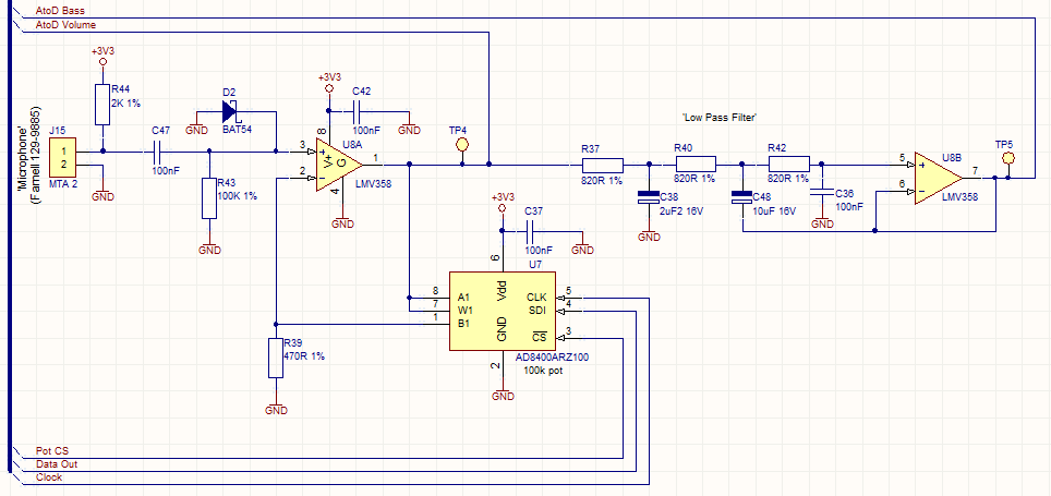
This circuit employs a digital potentiometer to enable the microcontroller to automatically adjust the circuit's gain according to the ambient audio volume. However, a standard potentiometer can be used if automatic adjustment is unnecessary. The low-pass filter design is...
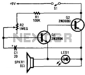
Two complementary transistors create a basic oscillator with a frequency range of approximately 0.5 to several Hz. This circuit serves as a metronome, timer, or pacer for exercise equipment. The oscillator circuit utilizes a pair of complementary transistors, typically one...

The clock described here is a simple single-digit nixie clock featuring interesting attributes without the use of complex components. It illustrates the feasibility of utilizing standard, low-voltage, general-purpose, small-signal transistors, such as the BC550, as nixie drivers. This might...
The digital lock shown below uses 4 common logic ICs to allow controlling a relay by entering a 4 digit number on a keypad. The first 4 outputs from the CD4017 decade counter (pins 3,2,4,7) are gated together with...
This project can be used for many different purposes. Probably the most used application would be to interface to any electronic project that requires a keypad. There are several ready made keypads on the market, but those work with...
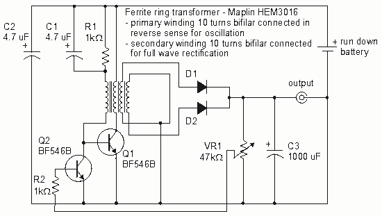
How to create a Joule Thief circuit to power a clock, including circuit details and tips for construction. The Joule Thief circuit is a simple and efficient boost converter that allows the extraction of usable voltage from low-voltage sources, such...