
Door lock Motor

The circuit under discussion involves a door lock motor with a resistance of approximately 2 ohms, which draws a current of 2.5A when powered by a 5V supply. This current is slightly above the maximum continuous output of the L293B motor driver, which is rated at 2A. However, since the motor is intended to operate only for brief intervals, this temporary overload does not pose a significant risk to the driver.
To effectively manage the power supply, a voltage regulator, specifically the LM7805, is utilized to convert a higher voltage of 14V down to the required 5V for the motor. The LM7805 is capable of delivering a peak output current of 2.5A, sufficient to meet the demands of the motor operation under the specified conditions. It is essential to note that the LM7805's output capacity is contingent upon the voltage differential; it can deliver its maximum current when the input voltage exceeds the output voltage by at least 9V. This ensures that the regulator operates within its safe limits while providing adequate power to the motor.
In summary, the circuit successfully integrates a door lock motor with a power supply system that includes a motor driver and a voltage regulator, allowing for efficient operation while maintaining component safety and reliability during short-duration tasks.The measured resistance of door lock motor was about 2 ohm. Therefore, supplying 5V, the current becomes 5v/2ohm= 2. 5A. Regarding that the peak output current of L293B is 2A, the current flowing inside the motor is slightly over 2A, but it does not occur any problem because the motor will be used just for several seconds. Voltage regulator (LM7805 ) was used to regulate the voltage from 14V to 5V. 7805`s peak output current is 2. 5A when the voltage difference between the input and the output is 9V (14-5=9V). Therefore 7805 can supply enough current for door lock motor. 🔗 External reference
Related Circuits
The primary objective of this design is to address a minor flaw in the well-known Fridge Door Alarm circuit, which has been available on this website since 1999 and has been constructed by numerous hobbyists. This circuit unfortunately ceases...
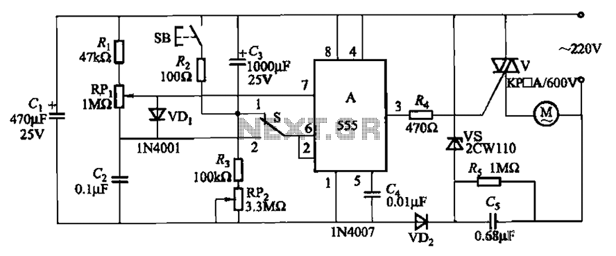
The circuit illustrated in Figure 3-12 incorporates variable speed and timing control functions. When switch S is set to position 1 and button SB is pressed, the motor initiates operation. After a predetermined delay, the motor automatically shuts down....
This circuit can be used to operate an electric strike or an electromagnetic lock on a door. It is not the door being opened/closed, but a small electromagnetic strike which unlocks the door. The opener has the following features...

After dismantling a Chinese copy of a Segway, an examination of the motor controller was conducted. After several hours of work with a multimeter, pen, paper, and KiCad, a block diagram and schematic of the motor controller were developed....
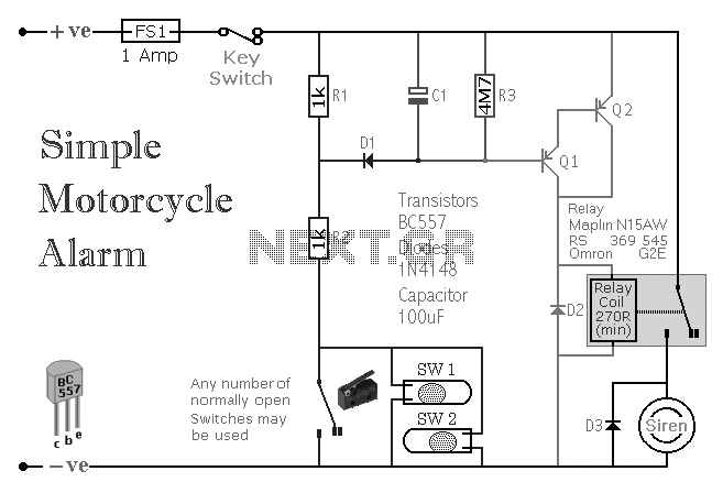
A simple transistor-based motorcycle alarm circuit. This circuit is easy to build and designed to operate at 12 volts. However, by replacing the relay with one that has a 6-volt coil, it can also provide protection at that voltage. The...

This is the power diagram for motor forward and reverse operation. To change the motor direction, one polarity must be altered, for example, changing R to S. For detailed information, please refer to the following. The described power diagram illustrates...