
Door Lock Wiring
5-wire door locks are more complex. When the switch is off, both the lock and unlock wires are grounded. When the switch is pushed to the unlock position, the unlock wire is disconnected from ground and connected to +12V, activating the actuator. The same principle applies to the lock wire, but with reversed voltage, moving the door lock actuators in the opposite direction. In this scenario, the factory relays must be cut, and aftermarket relays should be connected as illustrated. In the diagram, the "to switch" end of the wire is grounded, while the "to solenoid" end of the wire either locks or unlocks the doors when +12V is applied. In some vehicles, such as older Isuzu Rodeos, an additional solenoid may be required to enable the locking and unlocking of other doors. The driver's door lock does not contain an actuator; it functions as a switch, controlling the power locks of the other doors when the lock moves up and down. Actuators can be installed in virtually any vehicle lacking power locks, with one actuator required per lock. The circuit depicted below will manage all actuators, allowing simultaneous locking and unlocking of all doors. A grounded switch can also be included, enabling manual lock/unlock operations through the alarm. It is important to note that the diagram is designed for alarms that provide negative (ground) pulses for locking and unlocking. If the alarm being installed has positive outputs, the "85" terminals of the relays should be connected to ground (-). Caution is advised, as the diagrams are applicable to most GM, Chrysler, and Ford vehicles, but not all, necessitating a thorough check of all wires before making any connections. Additionally, there are alternative wiring configurations for factory locks that do not fit into the 3 or 5-wire categories, such as Ford Probes, which utilize different voltage levels, Toyota Camrys with child safety locks that employ diodes, and German vehicles, including Mercedes, that utilize vacuum door locks.
The integration of alarm systems with door lock actuators enhances vehicle security by providing automated locking and unlocking functionalities. The 3-wire and 5-wire systems exhibit distinct operational characteristics, requiring careful consideration during installation. The 3-wire system simplifies the process by allowing direct connections to the existing wiring without modification. In contrast, the 5-wire system necessitates the installation of relays to manage the voltage changes required for actuator activation.
For the 5-wire system, the proper configuration of relays is crucial. The relays must be wired such that when the switch is activated, the corresponding wire is energized with +12V, allowing the actuator to respond appropriately. The use of a grounded switch in conjunction with the alarm system provides an additional layer of control, enabling manual operation when necessary.
When implementing these systems, it is essential to verify the specific wiring configurations of the target vehicle, as variations exist across different makes and models. Utilizing a multimeter can aid in identifying the correct wiring scheme, ensuring compatibility with the chosen alarm system. Furthermore, attention must be paid to the power requirements of the actuators, ensuring that the vehicle's electrical system can support the added load without compromising performance.
In summary, the integration of alarm systems with door lock actuators enhances vehicle security and convenience. Proper understanding of the wiring configurations and relay systems is essential for successful installation and operation.3-wire door locks can be either positive (diagram below), or negative. There is either a constant ground or positive wire that makes contact with either the lock or unlock wire when the switch is pushed. The idea here is to add relays that will make the alarm`s lock and unlock outputs to do the same thing the switch does.
3-wire door locks are use d by a lot of Japanese cars. There is no need to cut the factory wires, just strip the insulation a bit and add the alarm wires (make sure you have a good connection - solder if possible). 5-wire door locks are a bit more complicated. While the switch is off, both wires (lock and unlock) are grounded. When the switch is pushed for example to the unlock position, the unlock wire gets disconnected from the ground, and connected to +12v, activating the actuator.
Same applies to the lock wire, but this time the voltage is reversed, moving the door lock actuators in the opposite direction. Here you have to cut the factory relays and hook up the aftermarket relays as shown. On the diagram, the "to switch" end of the wire is grounded and the "to solenoid" end of the wire either locks or unlocks the doors if given +12v.
On some cars such as older Isuzu Rodeos a solenoid has to be added in order to make the other doors lock and unlock. The driver`s door lock does not have an actuator, it acts as a switch, so that when the lock goes up and down, it controls the power locks in the other doors.
Actuators can be added to virtually any car that has no power locks. One actuator is needed per lock. The circuit below will control all the actuators, locking and unlocking all doors at the same time. A grounded switch can also be added where the alarm hooks up to lock/unlock the doors manually. Note that the diagram is for alarms that have negative (ground) pulses for lock and unlock. If the alarm you are installing has positive outputs, then simply hook up the "85" terminals of the relays to ground (-). Please keep in mind that the diagrams apply to most GM, Chrysler`s and Fords, but not ALL, so all wires should be checked before any connections are made.
There are other ways in which factory locks are wired up that don`t fall in either the 3 or 5-wire categories, such as Ford Probes which use different voltage levels, Toyota Camrys with child safety locks which use diodes, and Mercedes, and other German cars that use vacuum door locks. 🔗 External reference
Related Circuits
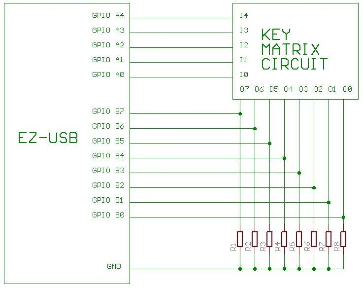
The circuit utilizes an AN2131 chip accompanied by the necessary support components, including a crystal oscillator and power regulators. The inputs and outputs of the key matrix were connected to the GPIO ports of the AN2131 through a protoboard....
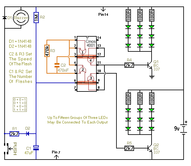
When the push switch is activated, the buzzer sounds, and the LEDs start to flash. For the hearing members of the household, the buzzer functions as a standard doorbell, providing reassurance to the visitor that the doorbell is operational....
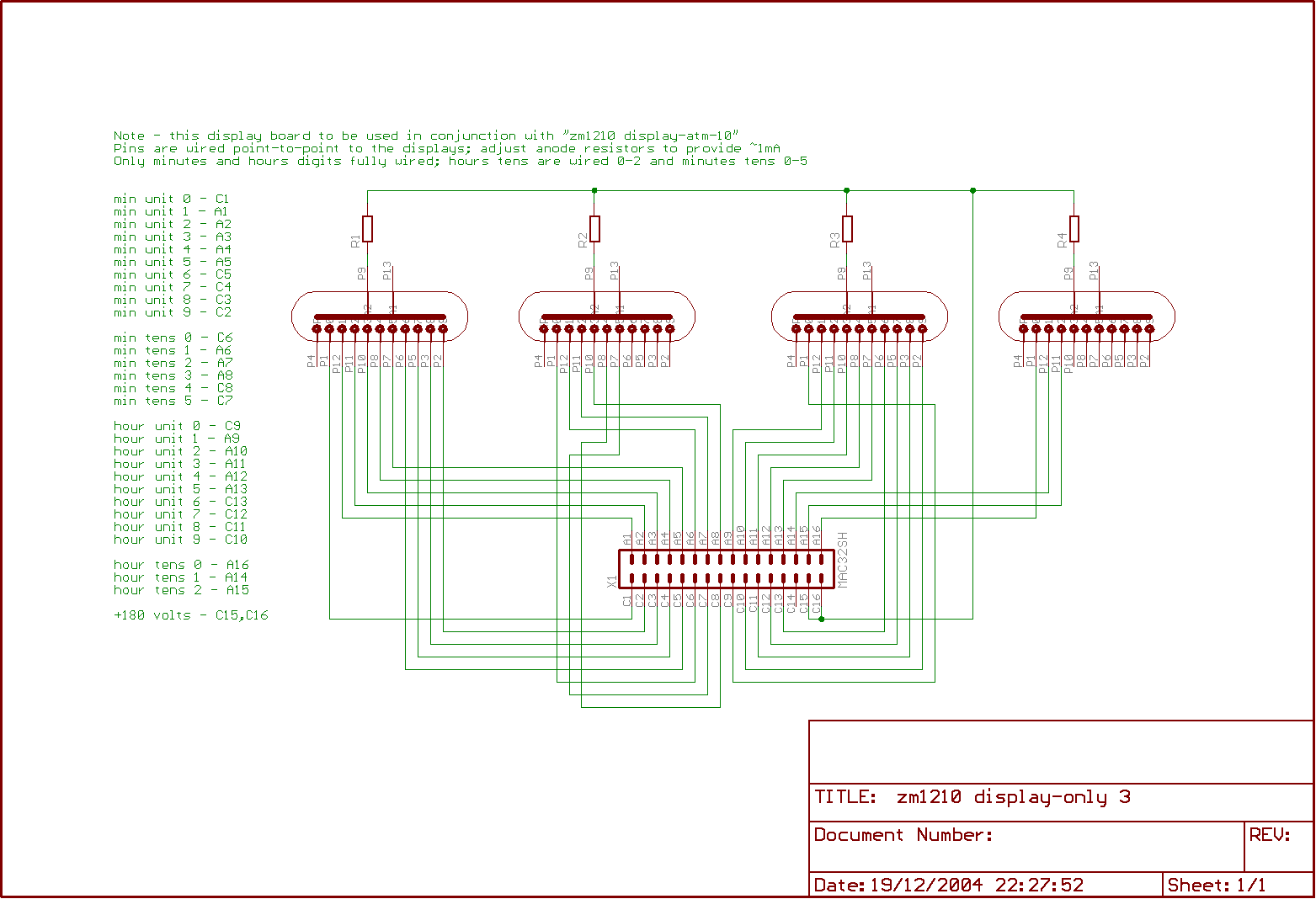
The clock is built on two boards; one contains the high-tension generator and the processor logic, while the other accommodates the tubes. This design offers a more compact layout compared to the previous model, although it does not save...
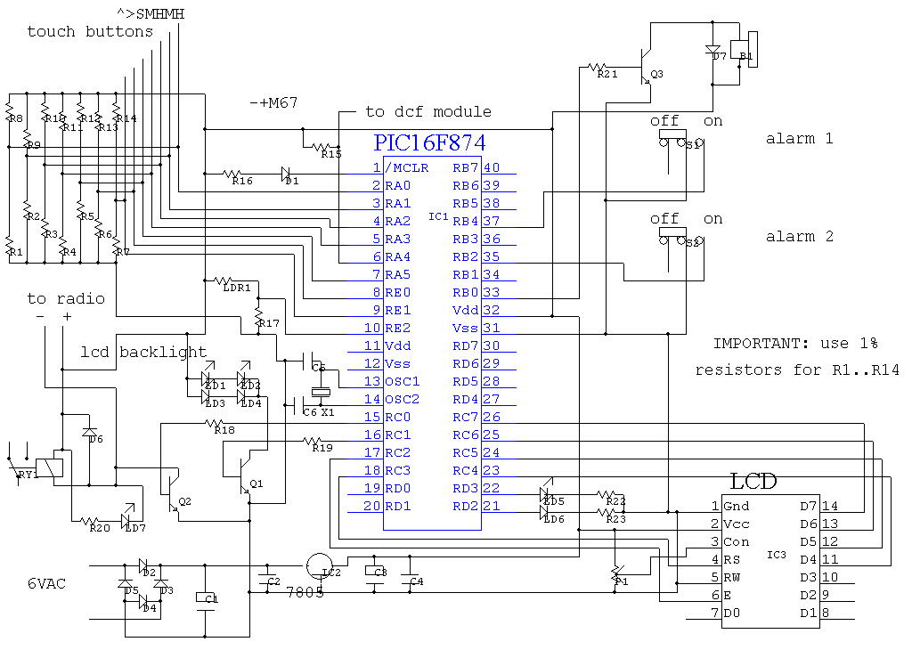
The program utilizes the built-in analog-to-digital (AD) converter of the PIC16F874 microcontroller for sensing touch buttons. The PIC features eight AD ports, with seven designated for the touch buttons and one for light measurement. To receive DCF signals, a...
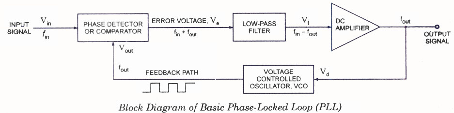
The operating principle of a Phase Locked Loop (PLL) is illustrated with a block diagram that includes a Phase Detector, Voltage Controlled Oscillator, and Low Pass Filter. A Phase Locked Loop (PLL) is an essential electronic circuit used in various...
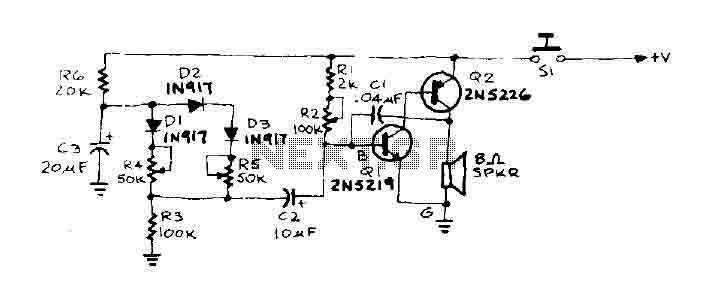
When the door is pushed, a whisper is heard that transitions to a higher frequency. The oscillator frequency is determined by the audio frequency coupling capacitance, C1, and the resistance connected between the base of transistor Q1 and ground....