
Doorbell Cascade

To implement the addition of a second doorbell, a comprehensive understanding of the existing doorbell circuit is essential. The typical doorbell system consists of a transformer, a push button, and a chime. The transformer converts the standard household voltage (usually 120V AC) to a lower voltage (typically 16V AC) suitable for the doorbell system.
In the proposed modification, the circuit needs to accommodate a second push button and chime without disrupting the functionality of the original doorbell. This can be achieved by wiring the second push button in parallel with the first one. When either button is pressed, the circuit will complete, allowing current to flow to the chime.
The installation involves the following steps:
1. **Power Supply**: Ensure the transformer can handle the load of both doorbells. If the existing transformer is rated for a lower wattage, it may need to be replaced with one that has a higher capacity.
2. **Wiring**: Use 18 AWG doorbell wire for the connections. Run a wire from the transformer to both push buttons, connecting them in parallel. This means that both buttons will share the same power source.
3. **Chime Connection**: Connect the output from both push buttons to the chime. The chime should also be compatible with the voltage provided by the transformer.
4. **Testing**: After completing the wiring, test each button individually to ensure that the chime activates correctly from both locations.
5. **Mounting**: Securely mount the second push button in the desired location, ensuring it is easily accessible.
By following these guidelines, the installation of a second doorbell can be accomplished efficiently, enhancing the functionality of the existing doorbell system.Sometimes you have to do it the hard way, even if doing it the easy way is an option. That is the case here. The intention is to add a second doorbell in.. 🔗 External reference
Related Circuits
.jpg)
The project outlines a method to add a cost-effective remote doorbell to an existing household doorbell system, particularly useful for individuals who may not hear the doorbell when in the basement. The household doorbell operates on a continuous 24VAC...

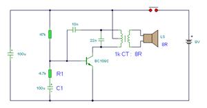
This is a circuit design for a doorbell that produces a bird-like sound. The circuit is controlled by an NPN transistor. The operation of the circuit begins when P1 is set to an experimental value, starting with approximately 220...

Figure 15-22 illustrates a doorbell system that consists of a monostable timing circuit, a password switch, a NAND gate circuit, and a sound output circuit. The operation of the circuit is designed such that when the password switch is...
It is easy to miss the sound of a doorbell while watching TV. This circuit addresses the issue by providing a visual indication, such as a lamp or an LED. Connecting a lamp directly in parallel with the doorbell...
The simple bell circuit without IC. It includes a doorbell circuit that can produce different sounds using integrated circuits, transistors, and resistors. The circuit utilizes a coded trigger mechanism to differentiate between various visitors. When the button is pressed,...
Doorbell for the Deaf. Circuit: Andy Collinson Email: [email protected]. This circuit provides a delayed visual indication when a doorbell switch is activated. The doorbell circuit designed for the deaf serves as a crucial tool for providing visual alerts in response...