
Doorbell for the Deaf

The doorbell circuit designed for the deaf serves as a crucial tool for providing visual alerts in response to doorbell activations. This circuit incorporates a delayed visual indication feature, which ensures that the alert is not only immediate but also sustained for a brief period, allowing individuals to notice it easily.
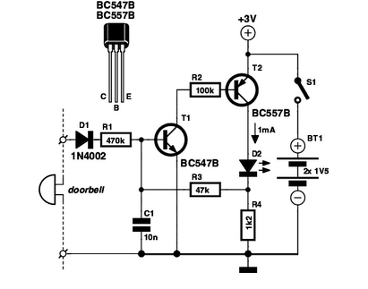
The core components of this circuit typically include a doorbell switch, a timer circuit, and a visual indicator, such as an LED or a series of LEDs. When the doorbell switch is pressed, it sends a signal to the timer circuit, which then activates the visual indicator. The timer is set to maintain the LED illumination for a predetermined duration, ensuring that the alert remains visible even if the individual is not immediately present at the door.
The circuit may utilize a 555 timer IC, which is widely used for timing applications. The configuration can be set up in a monostable mode, where the output remains high for a specific time interval after the doorbell switch is engaged. The time delay can be adjusted by changing the resistor and capacitor values connected to the timer IC.
Power supply considerations for this circuit are also important. It can be powered by a standard AC or DC source, depending on the specific design requirements. Proper voltage regulation and component ratings should be observed to ensure reliability and safety.
In summary, this doorbell circuit for the deaf not only enhances accessibility but also provides a practical solution for individuals who may not hear traditional doorbell sounds, ensuring they receive timely notifications of visitors.Doorbell for the Deaf. Circuit : Andy Collinson Email: [email protected] This circuit provides a delayed visual indication when a door bell switch is. 🔗 External reference
Related Circuits
This is a Doorbell Bird Voice Electro Suite designed to replace the old doorbell, providing a refreshing and exciting experience with a new doorbell system. The Doorbell Bird Voice Electro Suite is an innovative electronic circuit designed to enhance the...

An interesting hobby circuit of a crank doorbell. The circuit is built around a 555 timer and a musical piezo buzzer. It operates using a 9-volt battery supply; a single 9-volt PP3/6F22 compact battery is sufficient to power the...
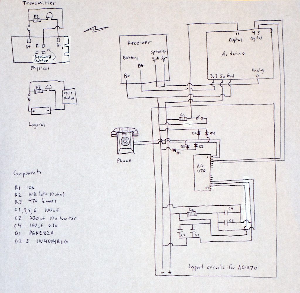
Any phone can be utilized for this project, so there is no need to worry about obtaining the same model as mentioned. If an antique Bakelite phone is chosen, basic restoration steps include cleaning it with a rag dampened...
Delay electronic doorbell circuit - touch doorbell amplifier circuit The delay electronic doorbell circuit is designed to provide a user-friendly interface for doorbell activation, utilizing a touch-sensitive amplifier circuit. This circuit typically incorporates a touch sensor that detects user interaction,...
If you are expecting an important visitor but need to step out for a moment, an electronic doorbell memory can be useful to check who rang the bell. An electronic doorbell memory system is designed to capture and store the...

This design outlines a door alarm circuit that utilizes an electronic system. It features a synthesized sound chip from Holtek, specifically the HT-2811, which reproduces the sound of a "ding-dong" chiming doorbell. The circuit also incorporates a CMOS 4026...