
Double five-band equalizer circuit

The double five-band equalizer circuit depicted in Figure 1-98 is designed to provide precise control over audio frequency response across two channels. The voltage amplifiers, represented by IC1 and IC14, amplify the input audio signals, allowing for enhanced signal processing capabilities. Each channel features a series of operational amplifiers (IC11, IC24, IC2, etc.) that work in tandem to adjust the gain and frequency response of the audio signals.
The analog inductor network formed by the various ICs (IC34, IC31, IC12, IC23, IC22, IC33, and IC32) plays a crucial role in shaping the equalization curve. By manipulating the inductance values, the circuit can effectively boost or cut specific frequency bands, allowing for tailored sound quality based on user preferences or specific audio environments.
Capacitors C7, C9, C11, and C13 are integral to the frequency response characteristics, as they interact with the resistors and inductors to create the desired filter characteristics. The design references Figure 1-93(a) for component values, ensuring compatibility and consistency in performance. The fixed resistor R2, set at 1 kΩ, stabilizes the circuit, while R1, set at 100 kΩ, aids in controlling the gain across the equalizer stages.
Overall, this double five-band equalizer circuit is an essential tool for audio processing, enabling users to achieve optimal sound quality through precise frequency adjustments.Figure 1-98 is a double five-band equalizer circuit composed of a second connection. FIG IC1 IC14 respectively equalizer per channel utility voltage amplifier; ICLl, IC24, IC 2 1, IC 34, IC31 and IC12.Ic23.IC22, IC33, Ic32 were two-channel analog inductor body; Island, C7, C9.Cll.C13 correspond to Figure 1-93 (a) of C1; C4, C6, C8.cIo -C12 correspond bar. R2 is fixed at 1kfl, Ri fixed 100koo
Related Circuits
The PR4403 is an advanced version of the PR4402 40mA LED driver. It features an additional input known as LS, which can be activated by pulling it low to illuminate the LED. This functionality simplifies the construction of an...
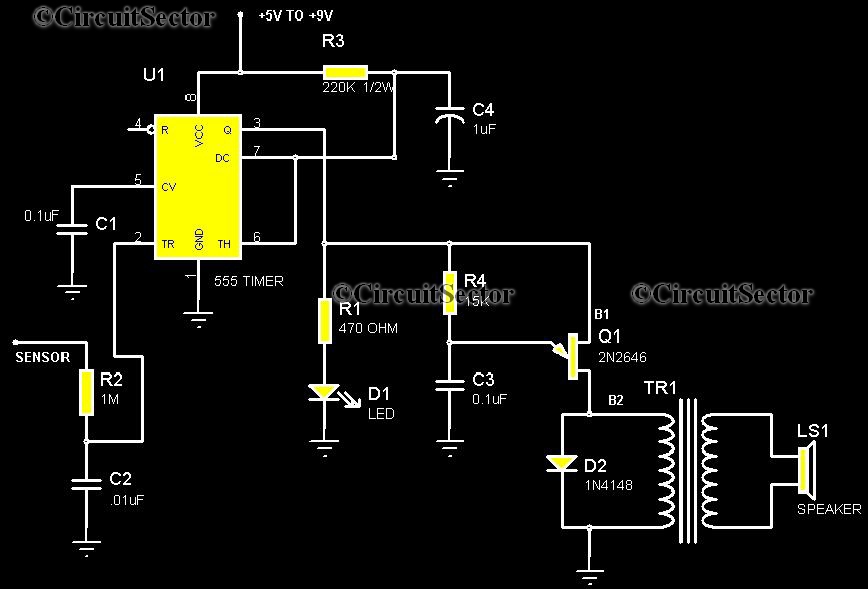
This is a highly sensitive touch plate circuit utilizing the NE555 timer IC, which activates a buzzer when a person touches the metal plate or hovers their hand above it. Compared to previously published touch control switch circuits, this...
This infrared (IR) remote extender enhances the range of most basic IR remotes operating at a 40KHz modulation frequency significantly. When in operation, the remote is aimed at the detector on the circuit, and a button is pressed. The...
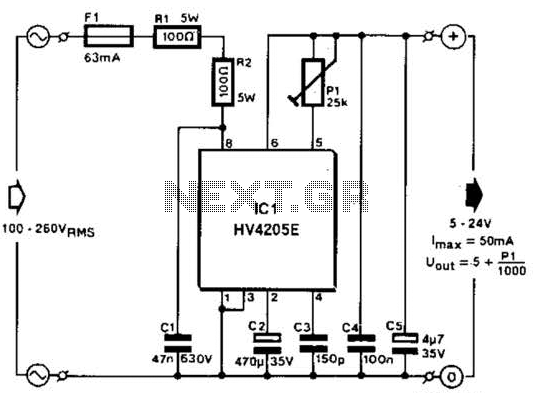
Direct derivation of 5 to 24 Vdc from AC mains without a transformer is possible with this circuit. Note that a direct mains connection to the DC output exists. Suitable safety precautions must be taken. This circuit design allows for...
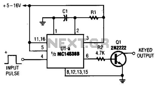
With switch SI in the off position, battery voltage is applied across timing capacitor CI, which remains charged while the rest of the circuitry is powered off. Transistor Q1, and consequently transistors Q2 through Q4, remain in an off...
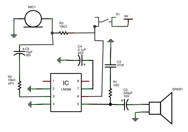
A button is utilized as a push-to-talk switch. While it generally functions correctly, there is a significant delay of approximately five seconds before any audio output is heard upon pressing the button. The described circuit involves a push-to-talk switch, which...