
NC visible laser modulation driver circuit

The laser tube drive circuit is designed to ensure stable operation of the laser system by continuously monitoring and adjusting the optical power output. The use of a photodiode allows for the detection of the laser beam intensity, providing feedback for the control system. However, due to the slow response time of the photodiode, it is not suitable for applications requiring rapid modulation of the laser output.
To address this limitation, the design incorporates a digital-to-analog converter (DAC) that translates digital signals into analog control voltages, thereby enabling precise adjustments to the laser power. The 3-wire serial interface facilitates communication between the DAC and the controlling microcontroller or digital signal processor, allowing for seamless integration into automated systems.
The visible laser modulation driver circuit is equipped with a separate digital input line (MOD) that can be used to trigger modulation events. The comparator (IC4) serves to compare the feedback signal from the photodiode with a reference voltage, ensuring that the output remains within specified limits. The open-drain output configuration allows for flexibility in interfacing with various components, including the transistor (VT1) that acts as a switch to pulse the laser diode (VD1) based on the digital commands received.
This architecture not only enhances the performance of the laser tube drive circuit but also allows for effective digital communication, making it suitable for applications in laser marking, engraving, and other industrial processes where precise control of laser output is crucial. The overall design emphasizes stability, responsiveness, and adaptability to varying operational demands.In the laser tube drive circuit are often provided with a photodiode, which generates a laser beam is proportional to the intensity (optical power) of the current, but in response to this type of photocell mostly relatively slow, generally can not track modulation peak light laser tube power. Therefore, this drive circuit is achieved by monitoring the average optical power to control the laser generator. NC visible laser modulation driver circuit is shown, which includes a digital to analog converter 10 3-wire serial interface (DAC), a visible light laser tube is used to control the output of a constant average optical power; a separate digital input line (MOD), an open-drain output by a comparator (IC4) and VTl, is fed to the laser diode VD1 pulse, digital communications.
Related Circuits

This is a UHF band TV antenna preamplifier circuit with a gain of 15 dB, built using a BF180 UHF transistor. The circuit is straightforward in design. The operational principle consists of two stages. The first stage features a...
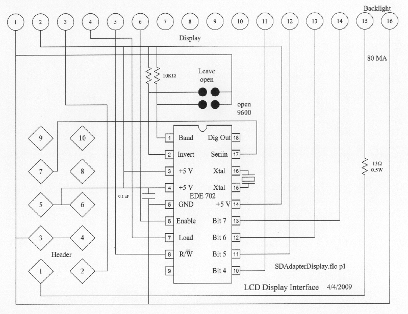
A purchase was made of the EDE702 along with an LED-backlit LCD character display. After acquiring the EDE702, it was determined that it lacked sufficient integration with HD44780-compatible displays to justify its cost. However, utilizing it was preferable to...

The circuit is constructed around a single integrated circuit (U1), specifically an MC3403P quad op-amp, three transistors (Q1-Q3), and several supporting components. It receives its input from the antenna (ANT1). The signal is processed through a high-pass filter composed...
The circuit operates as a photoelectric switch utilizing a photoresistor. It exhibits high sensitivity, particularly in controlling a light relay. Under low illumination, the transistor (VT) remains non-conductive. When the illumination reaches a certain threshold, the resistance of the...
The divider acts as the speaker's brain and is crucial for sound quality. The music amplifier's output signal must be processed through a wave filter element to divide it into specific frequency signals for each unit. A scientifically and...
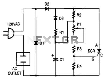
This circuit allows any standard household bulb to shimmer or blink. It is compatible with incandescent lights up to 200 W and operates on standard 120 Vac. The circuit employs a silicon-controlled rectifier (SCR) to create the shimmering effect....