
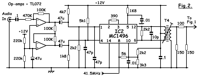
DOUBLE SIDEBAND SUPPRESSED CARRIER MODULATOR

In a typical AM modulation circuit, the fundamental principle involves the modulation of a carrier signal's amplitude in accordance with the information signal, which is often audio. The circuit consists of a carrier generator, typically an oscillator, which produces a high-frequency sine wave. This carrier signal is then mixed with the baseband signal, which contains the information to be transmitted.
The configuration of differential pairs is crucial in this setup, as it allows for precise control over the carrier signal's presence in the output. By applying specific offsets to these pairs, the circuit can introduce controlled amounts of the carrier signal into the output. This modulation can be fine-tuned to achieve the desired amplitude levels of the carrier, effectively allowing for the transmission of the audio signal over a radio frequency.
The modulation index, which is the ratio of the amplitude of the modulating signal to the amplitude of the carrier signal, plays a vital role in determining the quality and fidelity of the transmitted signal. Properly managing this index ensures that the output retains the integrity of the original audio signal while allowing the carrier to be appropriately modulated.
In summary, the design of an AM modulation circuit requires careful consideration of the carrier signal's amplitude and its interaction with the information signal. By utilizing differential pairs and applying offsets, the circuit can achieve the necessary modulation characteristics for effective communication.The basic current allows no carrier to be present in the output. By adding offsets to the carrier differential pairs, controlled amounts of carrier appear at the output. The amplitude becomes a function of the modulation signal-AM modulation. 🔗 External reference
Related Circuits
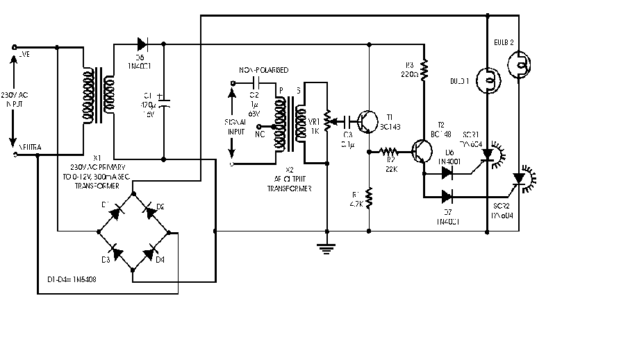
Audio light modulations add to the enjoyment of music during functions organised at home or outdoors. Presented here is one such simple circuit in which light is modulated using a small fraction of the audio output from the speaker...
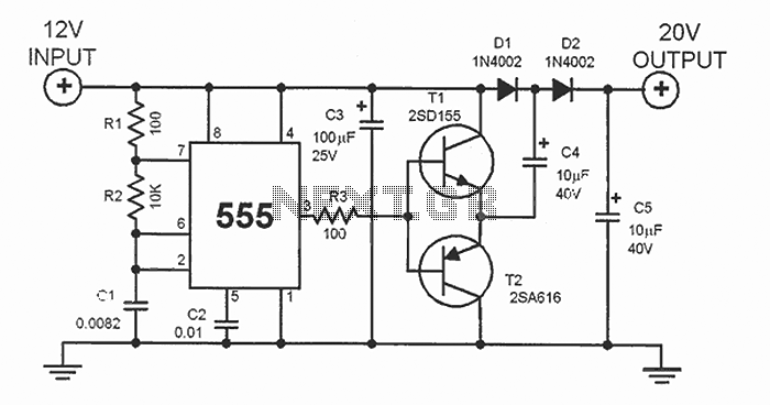
This DC voltage doubler circuit generates a voltage that is double the input supply voltage. It is beneficial when a higher voltage is required from a single lower voltage power source, particularly in applications with low current consumption. The DC...
The FM oscillator/modulator is a voltage-controlled oscillator that demonstrates a nearly linear relationship between output frequency and input voltage across a broad frequency deviation. It serves as an effective FM source with minimal additional components required. The device operates...
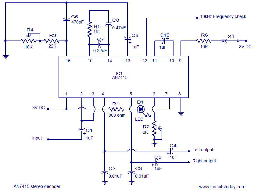
AN7415 based FM stereo demodulator circuit. 1.6 to 7V operating voltage range. High gain and low distortion. The AN7415 is a versatile integrated circuit designed for FM stereo demodulation applications. This circuit operates within a voltage range of 1.6 to...
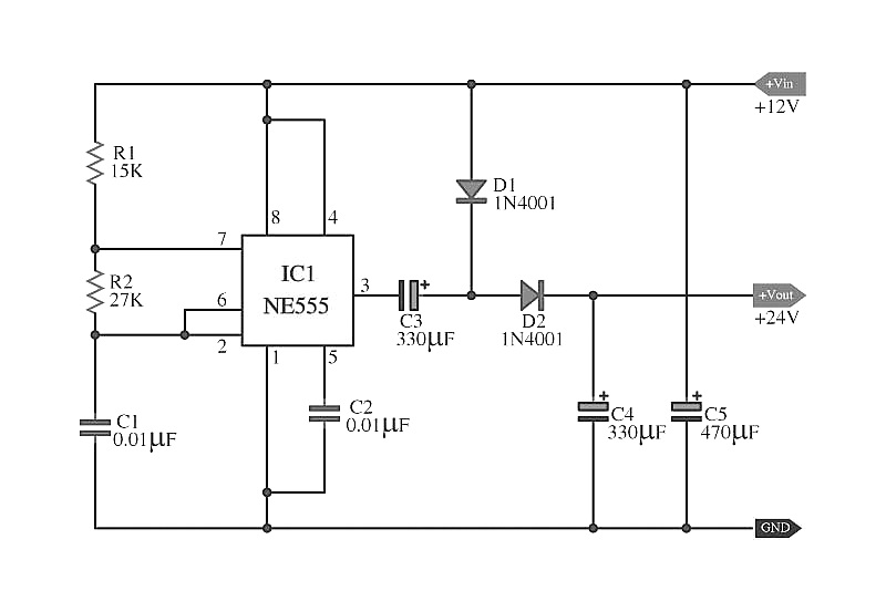
The capacitors C5 work in conjunction with IC1, while the resistors R1 and R2, along with capacitors C1, form an astable multivibrator square wave generator. This generator outputs a frequency of approximately 2 kHz from pin 3 of IC1....
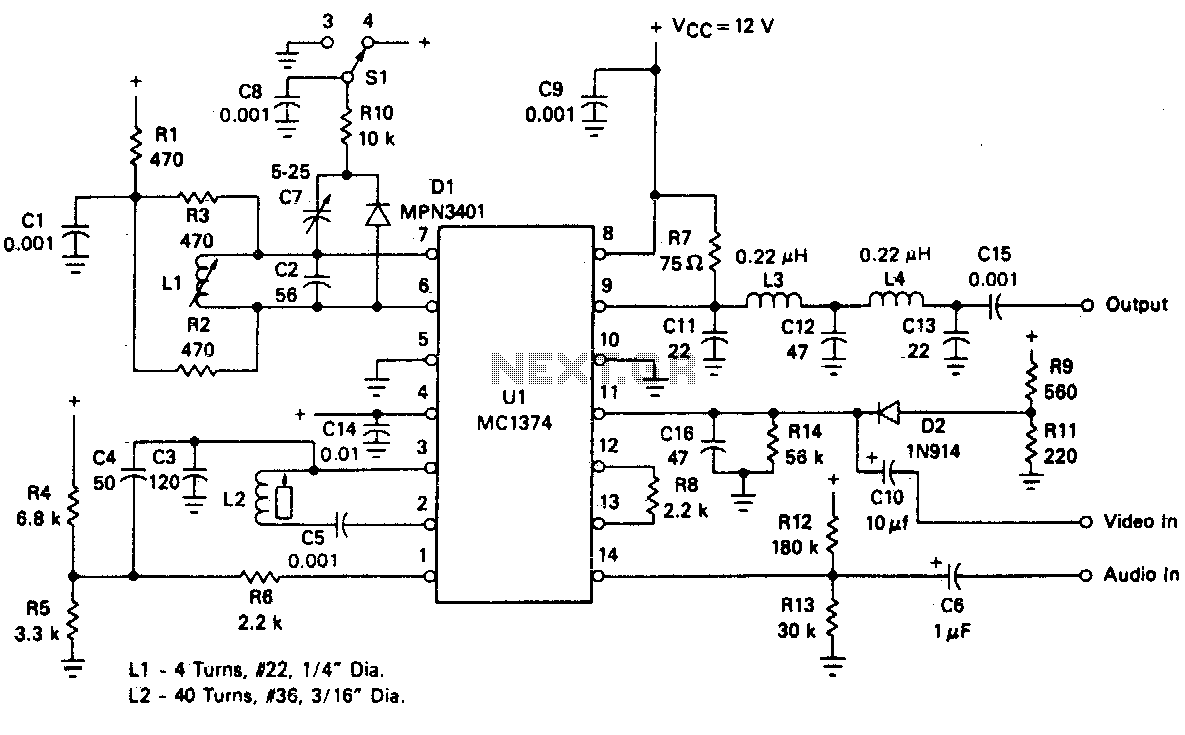
With the impending shutdown of the 405-line transmitter network, individuals with collections of early television sets must find new methods to supply them with appropriate signals. Regardless of the scheme implemented, a method for converting baseband audio and video...