
Audio Light Modulator circuit

The described circuit is designed to create an engaging audio-visual experience by modulating light in response to audio signals. The core function of this circuit is to take a small portion of the audio output from an audio amplifier and use it to control a light source, such as an LED or a lamp, effectively synchronizing light patterns with the audio output.
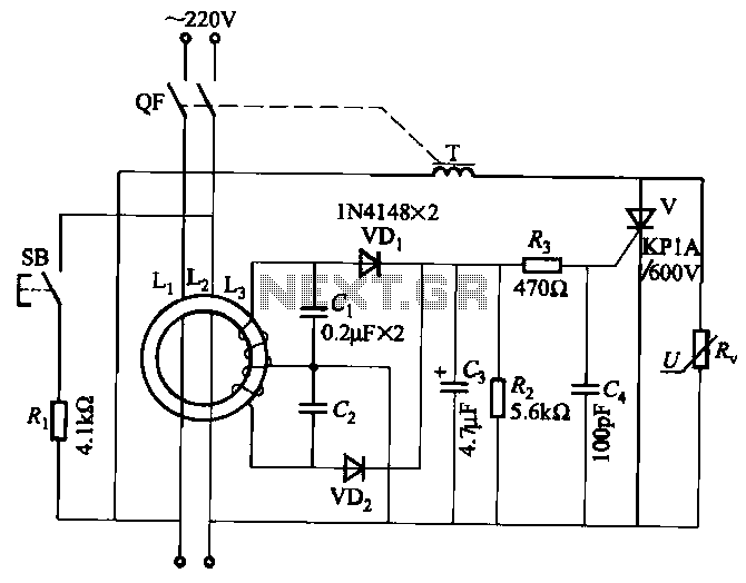
The audio signal from the speaker terminals is coupled to the circuit through a non-polarized capacitor, which serves to block any DC component while allowing the AC audio signal to pass. This is crucial for ensuring that only the audio frequencies affect the light modulation, preventing any potential DC offset from interfering with the operation of the circuit.
A transformer is incorporated into the circuit to provide electrical isolation between the audio amplifier and the light modulation circuit. This isolation is important for safety, as it minimizes the risk of shock from the mains voltage, which can be present in the circuit. The transformer steps down the audio signal to a manageable level suitable for processing by the subsequent components.
The sensitivity control potentiometer, designated as VR1, is strategically placed in the circuit to allow for adjustment based on the audio source level. By tuning this potentiometer, the user can set a threshold level for audio frequency detection, ensuring that the light modulation only activates when the audio signal exceeds a certain amplitude. This feature enhances the responsiveness of the circuit to dynamic changes in audio levels, making it more effective for various music genres and volume settings.
Furthermore, the circuit includes a diode bridge that converts the AC signal from the transformer into pulsating DC. This pulsating DC can be used to drive the light source, creating a flickering effect that corresponds to the audio input. The diode bridge also serves as a protective measure, providing a safeguard between the mains input and the pulsating DC output, thus protecting sensitive components from voltage spikes or surges.
Proper earthing of the circuit is emphasized as a critical safety measure. It is essential to ensure that all components are correctly grounded to prevent any potential electric shock hazards, especially given that the circuit interfaces with mains voltage.
In summary, this audio light modulation circuit effectively combines audio signals with light control, creating an immersive experience while prioritizing safety through isolation and proper electrical design practices.Audio light modulations add to the enjoyment of music during functions organised at home or outdoors. Presented here is one such simple circuit in which light is modulated using a small fraction of the audio output from the speaker terminals of the audio amplifier.
The output from the speaker terminals of audio amplifier is connected to a transformer (output transformer used in transistor radios) through a non-polarised capacitor. The use of transformer is essential for isolating the audio source from the circuit in The sensitivity control potentiometer VR1 provided in the input to transistor T1 may be adjusted to ensure that conduction takes place only after the AF exceeds certain amplitude.
This control has to be adjusted as per audio source level. The audio signal Proper earthing of the circuit is quite essential. The diode bridge provides pulsating DC output and acts as a guard circuit between the mains input and pulsating DC output. Extreme care is necessary to avoid any electric shock. 🔗 External reference
Related Circuits
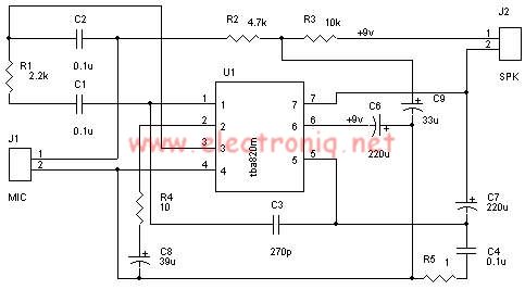
A very simple audio amplifier circuit can be designed using the TBA820M audio amplifier integrated circuit with just a few electronic components. This audio amplifier project features a high gain that allows for the detection of sounds underwater. The...
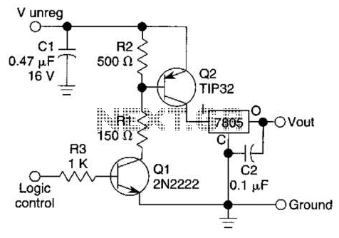
A logic level can control a 7805 regulator with this circuit. Q2 is a series switching transistor controlled by Q1. Q1 is turned on by a logic voltage to its base. This circuit utilizes a 7805 voltage regulator, which is...
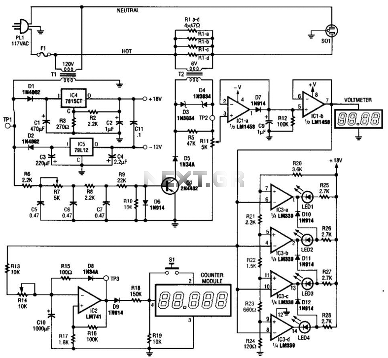
The ECM circuit comprises four sections, as illustrated in the block diagram. A power converter generates a voltage that correlates with the actual real power consumed by the load. This voltage supplies both a bar graph and a voltage-to-pulse...
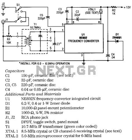
The NE602 chip, U1, contains oscillator and mixer stages. The mixer combines the oscillator signal with the input RF signal to produce signals whose frequencies are the sum and difference of the input frequencies. For example, an 8.5-MHz oscillator...
JBD3-10 leakage protection circuit The JBD3-10 leakage protection circuit is designed to detect and mitigate leakage currents in electrical systems, enhancing safety and preventing potential hazards. This circuit employs a differential current transformer that continuously monitors the current flowing through...
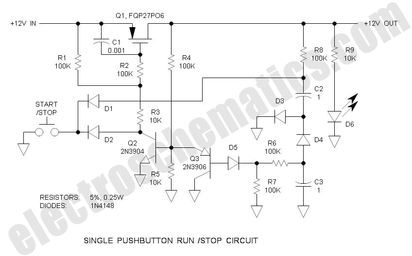
There are solutions to this problem—mechanical (push On/push Off switch), electromagnetic (latching relay), and electronic (CMOS logic), but few (if any) go... In addressing the problem of circuit control, several methods are available, including mechanical, electromagnetic, and electronic solutions. Mechanical...