
Stereo Tv Decoder Circuit

In this circuit, Q1 serves as the audio amplifier, responsible for boosting the audio signal to a suitable level for further processing or output. The audio amplifier typically operates in a linear region to ensure that the fidelity of the audio signal is maintained without distortion. The gain of Q1 can be set by selecting appropriate feedback resistors, allowing for flexibility in audio output levels.
U1 operates at a frequency of 31.5 kHz, which functions as a subcarrier for the audio signal. This frequency is particularly relevant in applications involving frequency modulation (FM) where multiplexing is required. The 38 kHz frequency mentioned in the context of FM multiplexing is often used in stereo broadcasts, where it helps in the separation of left and right audio channels. The 31.5 kHz subcarrier may be used to modulate additional information or channels within the audio signal.
The pilot frequency of 15.734 kHz is crucial for synchronization purposes. In FM broadcasting, a pilot tone is used to indicate the presence of a stereo signal. It allows receivers to lock onto the signal and demodulate it accurately, ensuring that the audio output is clear and free from interference. This frequency is typically generated using a crystal oscillator or a phase-locked loop (PLL) circuit to ensure stability and precision.
Overall, this circuit combines the functionalities of audio amplification and subcarrier generation to facilitate high-quality audio transmission, particularly in FM multiplexing applications. Proper design considerations, such as filtering and impedance matching, should be taken into account to optimize performance and minimize signal degradation. Ql is an audio amplifier and Ul is used as a 31.5-kHz subcarrier, which is similar to 38-kHz FM MPX. Pilot frequency is 15.734 kHz.
Related Circuits
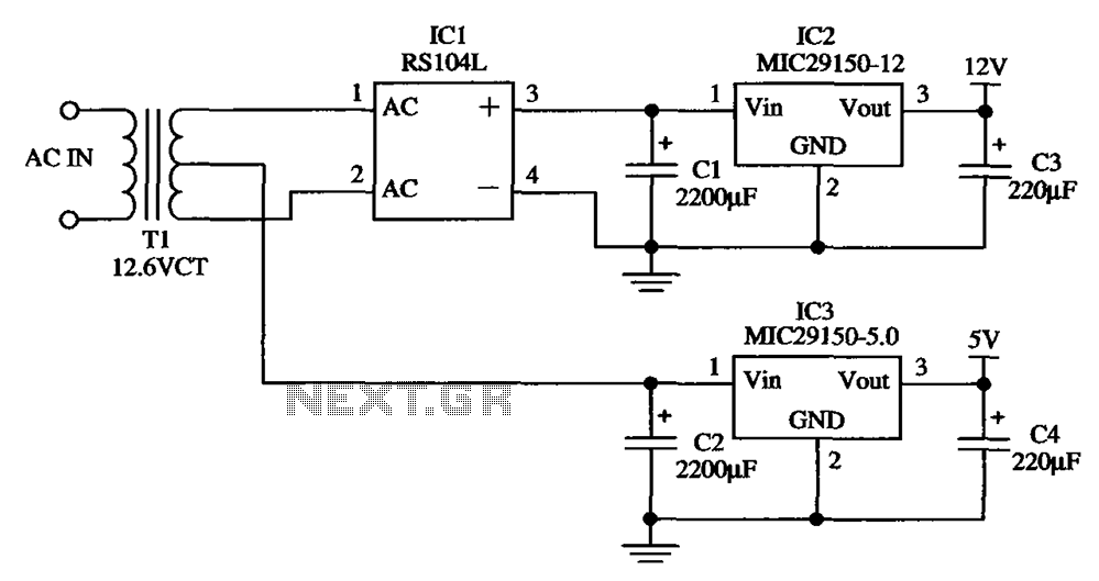
The low-cost dual output voltage regulator circuit is composed of two Micrel company regulators, the MIC29150-12 and the MIC29150-5.0. The dual output voltage regulator circuit utilizes the MIC29150 series from Micrel, which are low-dropout (LDO) voltage regulators designed for various...
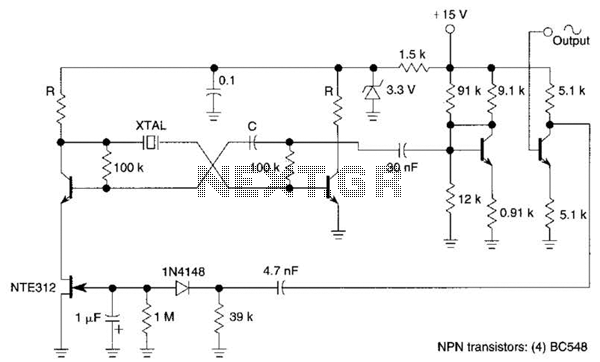
Q1, Q2, and the associated circuitry constitute a modified astable multivibrator where the loop gain is automatically adjusted to the threshold of oscillation by field effect transistor Q3. Q4 amplifies the signal at the collector of Q2 and isolates...
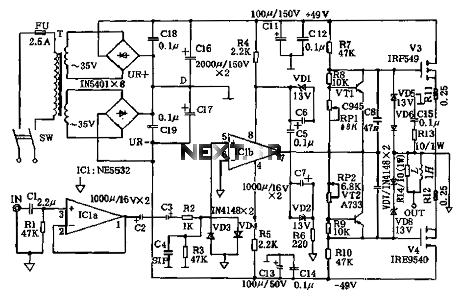
The amplifier circuit presented in this paper introduces a floating power supply aimed at increasing output power. The output power of the amplifier is influenced primarily by the final stage amplifier supply voltage. The circuit's principle is illustrated in...

The circuit activates a light corresponding to the first button pressed in a "Who's First" game. Three stages are illustrated, but the circuit can be expanded to accommodate any number of buttons and lamps. The described circuit operates as a...
This circuit is designed to achieve exceptional popularity, as evidenced by its record-breaking views and comments on the referenced website. As of May 3, 2013, it has garnered 760,191 views and 412 comments, with 116 views recorded on that...
This page is browser-friendly. To enhance readability, adjust your browser window to be narrower than the full screen. The page consists of two parts: the first part features a basic program demonstrating the RFID reader's functionality, while the second...