
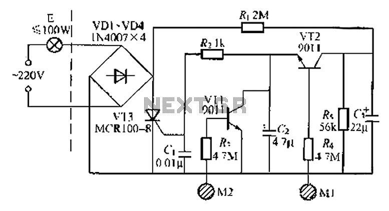
Doubling rectifier circuit in negative ion generator application circuit

The doubling rectifier circuit is an essential component in negative ion generator applications, where it plays a crucial role in converting alternating current (AC) to direct current (DC) while also increasing the voltage level. This circuit typically utilizes a combination of diodes and capacitors to achieve its rectification and voltage doubling functions.
In a standard configuration, the circuit consists of two diodes arranged in a full-wave rectifier setup. The input AC voltage is applied to the anodes of the diodes, which allows current to flow through them during both halves of the AC cycle. The output from the cathodes of the diodes is then smoothed by a capacitor, which helps to reduce the ripple in the DC output.
To achieve voltage doubling, an additional capacitor is employed to store energy during the rectification process. When the AC voltage reaches its peak, the first diode conducts and charges the capacitor. During the next half cycle, the second diode becomes forward-biased, allowing the capacitor to discharge and effectively doubling the output voltage.
This configuration is particularly advantageous in negative ion generator circuits, as it provides the high voltage necessary for ionization processes while maintaining a compact design. The use of high-voltage rated diodes and capacitors is critical to ensure reliability and efficiency in the circuit operation.
Overall, the doubling rectifier circuit is integral to the performance of negative ion generators, enabling them to produce the desired ion concentration levels for various applications, including air purification and environmental enhancement. Proper selection of components and careful circuit design are essential to optimize the performance and longevity of the system.Doubling rectifier circuit in negative ion generator application circuit
Related Circuits
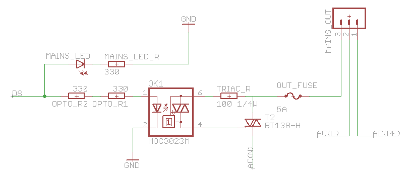
The heatsink on the triac is somewhat unclear. A maximum value of 10°C/W has been calculated, which raises concerns. The calculation is as follows: (maximum temperature - room temperature) / (maximum on-stage voltage * (milliamps / voltage) - junction-to-base...
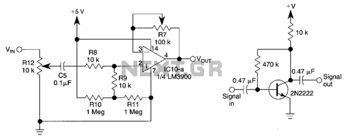
This circuit utilizes one-quarter of an LM3900 to create a simple variable-gain front end for an oscilloscope. R7 serves as the gain control. Additionally, a basic preamplifier is included for applications requiring more than 10X gain. The circuit employs the...
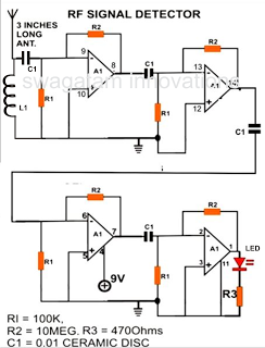
A simple electronic circuit project is presented that can be constructed by any school student for display at a school science fair. The proposed circuit is a high-gain operational amplifier (op-amp) amplifier designed to detect the slightest RF disturbances...
Built around a single 8038 waveform generator IC, this circuit produces sine, square or triangle waves from 20Hz to 200kHz in four switched ranges. There are both high and low level outputs which may be adjusted with the level...
A good performance is achieved with a two-wire connection for a double touch switch that can function even if there is a break in the left part of the line. This switch is designed for general lighting control, such...
In this circuit, a simple calculator, in conjunction with a COB (chip-on-board) from an analogue quartz clock, is used to make a telephone call meter. The calculator enables conversion of STD/ISD calls to local call equivalents and always displays...