
Drive relay with AVR microcontroller

To implement a relay driver circuit using a transistor, the following components and configuration are typically utilized. The basic arrangement consists of a microcontroller, a transistor (such as a NPN type), a relay, a diode, and a resistor.
1. **Microcontroller**: The microcontroller outputs a low current signal (typically 5V) to control the transistor. This signal is connected to the base of the transistor through a current-limiting resistor, which is usually in the range of 1kΩ to 10kΩ.
2. **Transistor**: The NPN transistor acts as a switch. When the microcontroller sends a high signal to the base, the transistor turns on, allowing current to flow from the collector to the emitter. This current is sufficient to energize the relay coil.
3. **Relay**: The relay is connected between the collector of the transistor and a power supply. When the transistor is activated, the relay coil is energized, closing the relay contacts and allowing current to flow to the load (lamp, motor, etc.).
4. **Diode**: A flyback diode is placed in parallel with the relay coil, oriented to allow current to flow in the reverse direction when the relay is de-energized. This protects the transistor from voltage spikes generated by the inductive load of the relay.
5. **Integrated Circuits**: For controlling multiple relays, using ICs like the ULN2003 or ULN2803 is advantageous. These chips contain multiple Darlington pairs, enabling them to drive several loads simultaneously. Each output can handle up to 500mA, making them suitable for larger applications.
This configuration allows for safe and efficient control of relays and other inductive loads, ensuring that the microcontroller operates within its current limits while effectively managing higher power devices.To drive relay you need more than 20mA the current can one pin drive. This is why you cannot connect relay directly to microcontrollers pin. To drive relay you need to connect simple amplifier made of one transistor. This circuit is more general as instead relay you can connect any other load like lamps, DC motors if you need to control more t han one relay, you might consider using ICs like ULN2003 or ULN2803. These ICs haveDarlingtontransistors inside and can drive up to 500mA each. We aim to transmit more information by carrying articles. Please send us an E-mail to wanghuali@hqew. net within 15 days if we are involved in the problems of article content, copyright or other problems. We will delete it soon. 🔗 External reference
Related Circuits

Schematic and operation of a microcontroller-based driver circuit for large 1-Wire networks; includes software flowcharts and scope traces. The schematic details a microcontroller-driven circuit designed to manage extensive 1-Wire networks, which are commonly used for communication and control in various...
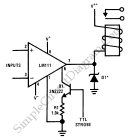
The LM111 comparator can be utilized to design a relay driver with a TTL strobe, which enhances control over the relay driver. The strobe signal can be used to manage the relay operation more effectively. The LM111 is a high-speed...
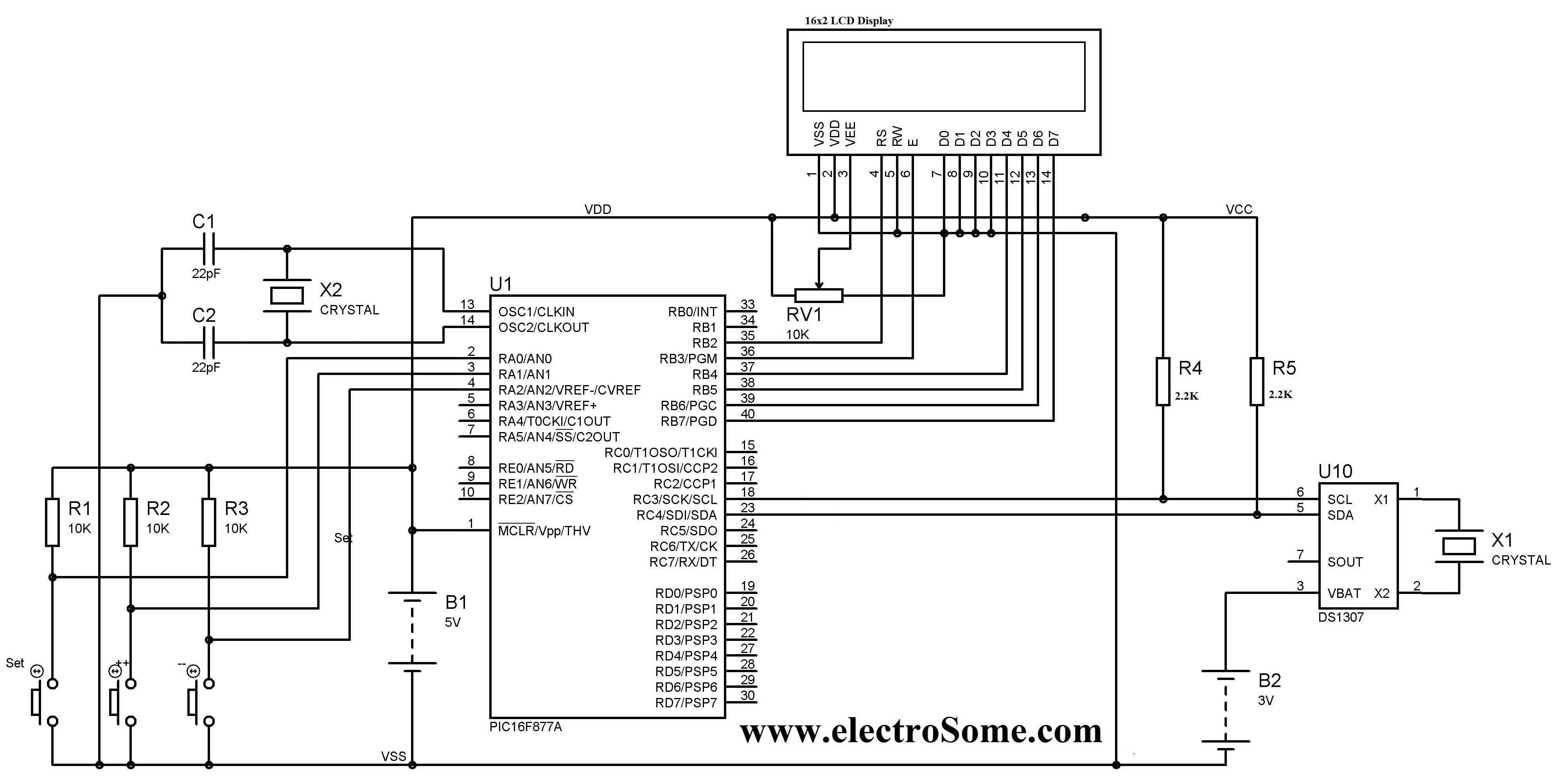
A digital clock can be constructed using a PIC microcontroller, DS1307 real-time clock (RTC), and a 16x2 LCD display. The DS1307 RTC operates in either 24-hour or 12-hour mode with an AM/PM indicator. It adjusts automatically for months with...
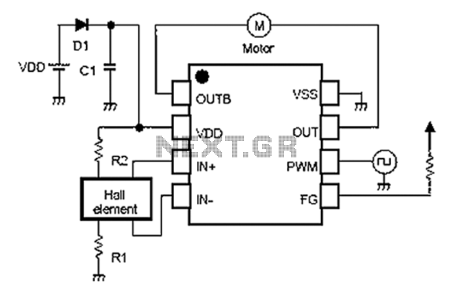
A simple single-phase brushless DC motor drive using the NJU7365 motor driver IC from New Japan Radio Co., Ltd. The NJU7365 is designed for single-phase motor applications and features built-in MOSFET motor drives, direct PWM input, FG output, and...
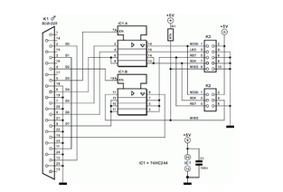
This circuit is designed to program AVR controllers, specifically the AT90S1200, using a parallel port. The circuit is very straightforward. IC1 serves as a buffer. The circuit operates by interfacing the parallel port of a computer with the AVR microcontroller....

This page outlines a project that utilizes an audio signal to control an RC servo. The movement of the servo is proportional to the loudness of the sound. This concept is particularly applicable for creating animated mouths for talking...