
Squib-firing circuit
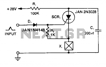
The described circuit is a typical example of a squib firing mechanism utilizing a capacitor, a silicon-controlled rectifier (SCR), and a diode for gate protection. The operation begins with capacitor C1 being charged to a voltage of +28 V through resistor R1, which limits the current and controls the charging time of the capacitor. This capacitor serves as an energy storage element, accumulating charge until needed for firing the squib.
When a positive pulse of 1 mA is applied to the gate of SCR1, the SCR enters its conductive state, allowing current to flow from C1 to the squib load X1. This action results in a rapid increase in voltage at the cathode of the SCR, which is directly connected to the squib load. The immediate rise in cathode voltage to +28 V indicates that the squib is now energized and ready to initiate its function, typically the detonation of an explosive device or the activation of a pyrotechnic element.
Diode D1 plays a crucial role in protecting the gate of SCR1. As the cathode voltage rises, D1 allows the gate voltage to follow suit, ensuring that the gate-to-cathode voltage remains within safe operating limits. This prevents damage to the SCR that could occur if the gate were to experience a negative voltage relative to the cathode.
An important feature of this circuit is its self-resetting capability. Once the squib has been fired and C1 has discharged, the current flowing through R1 becomes insufficient to maintain the SCR in its conducting state, as it falls below the holding current threshold. Consequently, SCR1 automatically turns off, allowing capacitor C1 to begin recharging for future use. This design ensures that the circuit is ready for subsequent firings without the need for manual intervention, enhancing operational efficiency and reliability in applications where repeated firing may be necessary.Capacitor Cl is charged to +28 V through Rl and stores energy for firing the squib. A positive pulse of 1 mA applied to the gate of SCR1 will cause it to conduct, discharging Cl into the squib load XI. With the load in the cathode circuit, the cathode rises immediately to + 28 V as soon as the SCR is triggered on.
DiodeD1 decouples the gate from the gate trigger source, allowing the gate to rise in potential along with the cathode so that the negative gate-to-cathode voltage rating is not exceeded. This circuit will reset itself after test firing, since the available current through Rl is less than the holding current of the SCR. After Cl has been discharged, the SCR automatically turns off—allowing Cl to recharge. 🔗 External reference
Related Circuits
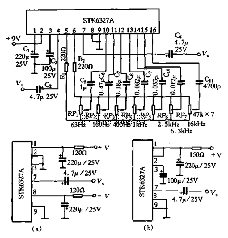
After the universal application of graphic equalizers, a new type of equalizer known as the parametric equalizer has emerged. This equalizer differs in its internal circuit structure and utilizes an external adjustment method that sets it apart from traditional...
This circuit is a 6-zone alarm system designed for independent operation, suitable for small office or home environments. It can be adapted to utilize a combination lock or keypad for setting and resetting the alarm. All zones, Z1 to...
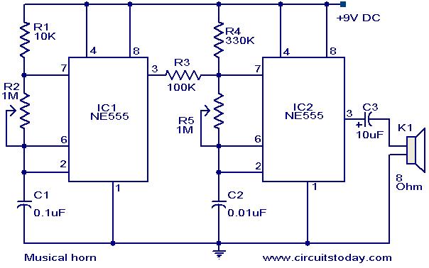
This document outlines a straightforward circuit diagram for a musical horn utilizing two NE555 integrated circuits (ICs). Both ICs are configured as astable multivibrators. The output from the first multivibrator is connected to the discharge pin (pin 7) of...
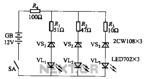
When the supply voltage falls below 10.2V, the yellow light-emitting diode (LED) VLi illuminates, indicating that the storage pool can no longer continue to discharge. Additionally, when the voltage exceeds 16.2V, the yellow, green, and red light-emitting diodes (LEDs)...
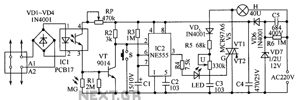
The telephone table lamp is designed to automatically illuminate during night ringing or when the phone is off-hook. After hanging up, the lamp will extinguish after a delay of 45 seconds. It is typically used as a general-purpose lamp...
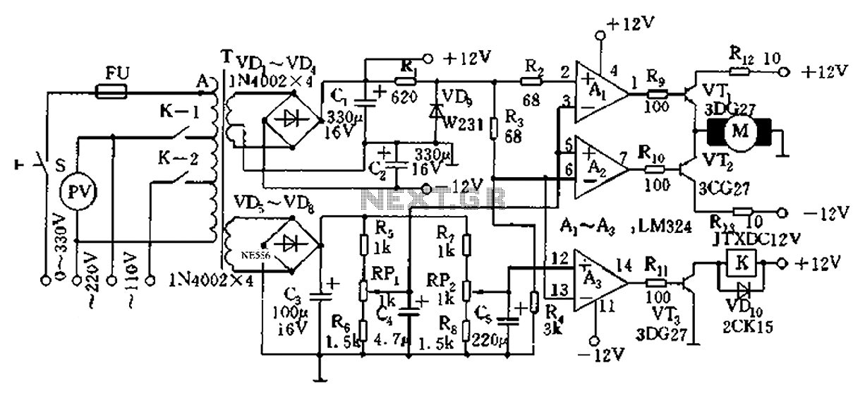
Automatic AC voltage regulator circuit TXD1742 with continuous adjustment. The TXD1742 is an automatic AC voltage regulator circuit designed to provide continuous voltage adjustment, ensuring stable output voltage in varying load conditions. This circuit is particularly useful in applications where...