
Dualxed cmos flasher
The circuit utilizes a series of inverters to create a multivibrator configuration that produces a square wave output. The multivibrator is formed by connecting two inverters, IC1-a and IC1-b, in a feedback loop, which generates oscillation. The output from IC1-b is fed into IC1-c, which serves as a buffer to prevent loading effects and ensure consistent voltage levels are maintained for subsequent stages.
IC1-d is configured to produce an output that is the logical inverse of the buffer output from IC1-c. This is achieved by connecting the output of IC1-c to the input of IC1-d, which results in a high output from IC1-d when IC1-c outputs low, and vice versa. The alternating states of pins 6 and 8 create a visual indication of the oscillation through two LEDs connected in reverse polarity. When one LED is forward-biased (and thus lit), the other is reverse-biased (and thus off), creating the appearance of the light "jumping" between the two LEDs.
The inclusion of a 470-ohm current-limiting resistor is crucial for protecting the LEDs from excessive current, which could lead to burnout. The specific value of the resistor may require adjustment based on the supply voltage to ensure that the LEDs operate within their optimal current range for maximum brightness without exceeding their rated limits.
Furthermore, the switching rate of the multivibrator can be fine-tuned by varying the capacitance in the timing circuit. Increasing the capacitance will slow down the switching rate, while decreasing it will accelerate the oscillation frequency. This flexibility allows for customization of the light display effect, making the circuit adaptable to various applications where visual signaling is required.Inverters ICl-a and ICl-b form a multivibrator and ICl-c is a buffer. Inverter ICl-d is connected so that its output is opposite that of ICl-c; when pin 6 is high, then pin 8 is low and vice versa. Because pins 6 and 8 are constantly changing state, first one LED and then the other is on since they are connected in reverse.
The light seems to jump back and forth between the LED"s, The 470-ohm resistor limits LED current Depending upon the supply voltage used, the value of the resistor may have to be changed to obtain maximum light output. To change the switching rate, change the value of the capacitor. 🔗 External reference
Related Circuits
This circuit enables car headlights to flash on and off simultaneously or alternately. It is based on the 555 timer operating in astable mode. The output of the 555 timer will go high for an adjustable period and then...
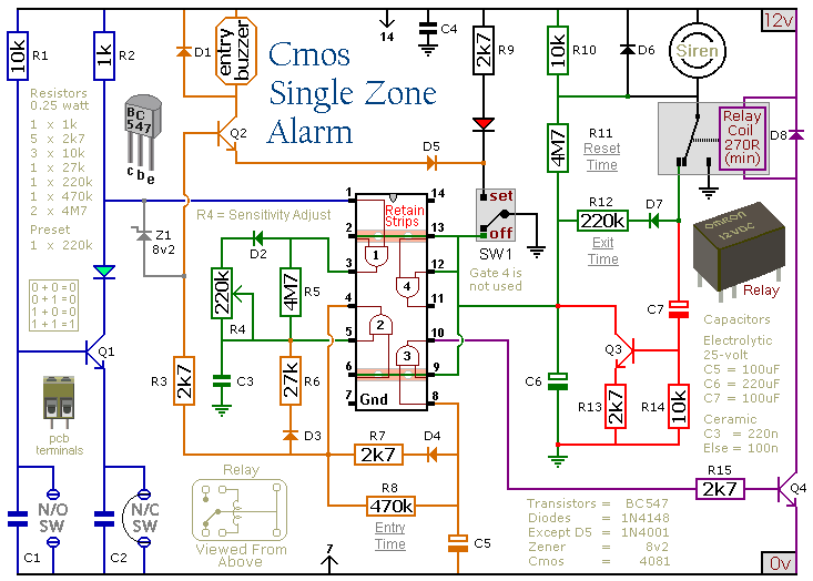
This circuit features automatic Exit/Entry delays, timed Bell Cut-off and System Reset. It has provision for normally open and normally closed switches and will accommodate the usual input devices such as Foil Tape, Pressure Mats, Magnetic Reed Contacts, Passive...
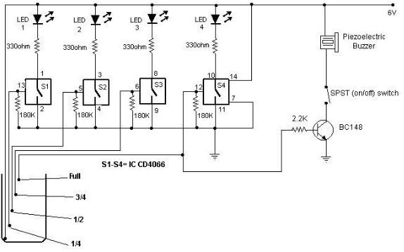
A low-cost water level indicator circuit can be designed using this schematic. This water level indicator utilizes a CMOS IC, the CD4066, to indicate the amount of water present in an overhead tank and provides an alarm when the...
The concept of this economical flashing LED indicator is straightforward. It employs a low-frequency oscillator to drive two LEDs connected in anti-parallel. In the circuit diagram, it can be observed that the current flows for a brief duration with...
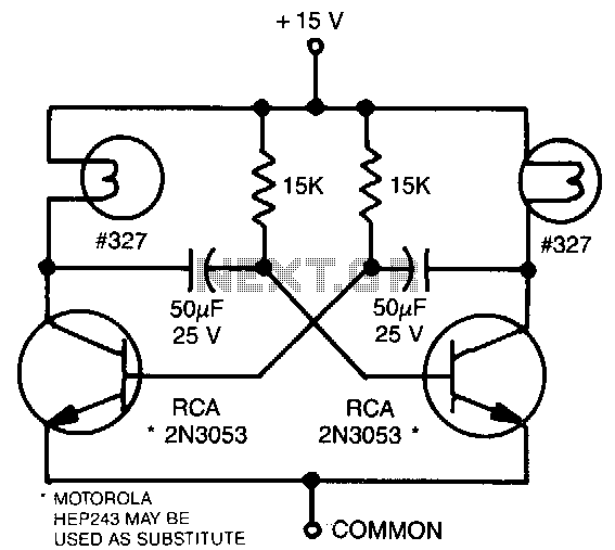
This astable multivibrator utilizes incandescent lamps instead of collector load resistors. The lamps flash on and off alternately. The circuit operates as an astable multivibrator, which is a type of oscillator that continuously switches between its high and low states...

A CMOS timer generates true square waves because, unlike the bipolar 555, its output swings from rail to rail. The component values shown give a frequency of about 400 Hz. The CMOS timer circuit operates by utilizing complementary metal-oxide-semiconductor technology...