
Dynamic Audio Mixer

The dynamic mixer circuit is designed to effectively blend two audio signals, where the primary input (Input A) directly influences the gain of the secondary input (Input B). This is accomplished through a feedback mechanism that utilizes an averaging function implemented in Integrated Circuit 1 (IC1). The choice of IC1 as either an NE571N or NE570N is significant due to their specific functionalities in audio processing, particularly in handling dynamic range compression.
The resistors R1, R2, and R3 are crucial for setting the levels of each input signal. R1 ensures that Input A is properly conditioned before mixing, while R2 adjusts the level of Input B that feeds into the modulator, allowing for precise control over the gain modulation process. R3 is responsible for managing the modulating signal's amplitude, ensuring that the gain adjustment is responsive to variations in Input A.
The average AC signal at pin 2 of IC1 is pivotal, as it dictates the output level at pin 3, effectively controlling the gain of Input B based on the amplitude of Input A. This dynamic relationship allows the mixer to adaptively respond to the audio signals, providing a more integrated sound.
The processed primary signal is transmitted to IC2, an NE5534N low-noise operational amplifier, through capacitor C1 and resistor R7. This operational amplifier is known for its high fidelity and low distortion, making it suitable for audio applications. The gain-modulated signal from IC1 is introduced at pin 5 of IC2, where both signals are summed to create the final output.
To accommodate user adjustments, potentiometers R4 and R6 are incorporated. R4 allows for fine-tuning of the DC offset, ensuring that the mixed output is centered appropriately within the desired voltage range. R6 is used to minimize distortion, enhancing the overall audio quality of the mixed signal.
Finally, the filtering section composed of IC3, capacitor C7, resistors R14 and R15, and diodes D1 and D2 is essential for refining the output signal. This filter serves to eliminate unwanted noise and artifacts that may arise during the mixing process, ensuring that the final audio output is clean and professional-grade. The careful selection of components and their arrangement in this dynamic mixer circuit exemplifies a well-thought-out approach to audio signal processing. The dynamic mixer combines two audio inputs by adding the primary signal, Input A, to a gain-controlled signal, Input B . The unusual aspect of this circuit is that the average voltage level of Input A controls the gain of Input B. IC1 has the averaging function and many of the specialized gain blocks that the circuit requires· Rl sets the level of the primary input, Input A, to be passed to the output.
R2 governs Input B"s level to the modulator, while R3 sets the level of the modulating signal. IC1 can be either an NE571N or an NE570N. The average ac signal at pin 2 controls the amount of signal that shows up at ICl"s output, pin 3. The primary signal gets to IC2, an NE5534N low-noise op amp, via CI and R7; the gain-modulated secondary signal arrives via pin 5 of IC1. IC2 sums the two signals. Potentiometers R4 and R6 make dc-offset and distortion adjustments, respectively. IC3, C7, R14, R15, Dl, and D2 form a filter for IC1.
Related Circuits
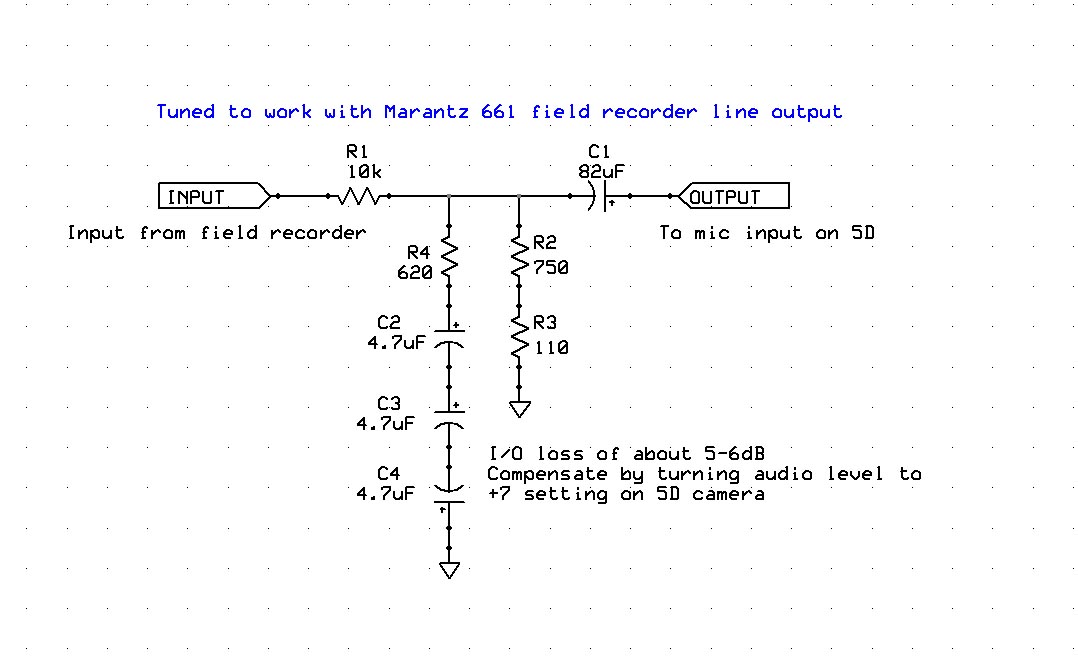
Enhancing the audio quality of the Canon 5D Mark II to achieve usable production audio involves several key steps. The initial phase of this engineering project focuses on data collection, specifically measuring the input frequency response of the 5D....
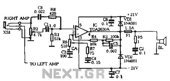
The circuit comprises two main components: the Lisheng power amplifier and the rectifier filter section. The stereo audio power amplifier circuit diagram, depicted in Figure 5-85, illustrates only one channel, with the other channel being identical. The audio signal...
The objective of this project was to design a small, portable mixer powered by a 9V PP3 battery while maintaining high-quality performance. The mixer consists of three main modules that can be varied in number and/or arrangement to meet...
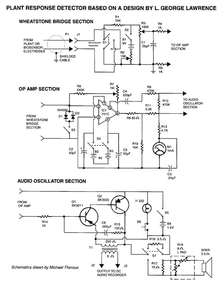
There is substantial evidence suggesting that certain forms of communication and energy exist beyond the traditional electromagnetic spectrum, of which we may have exemplary instances. The exploration of communications and energies beyond the conventional electromagnetic spectrum involves understanding various phenomena...
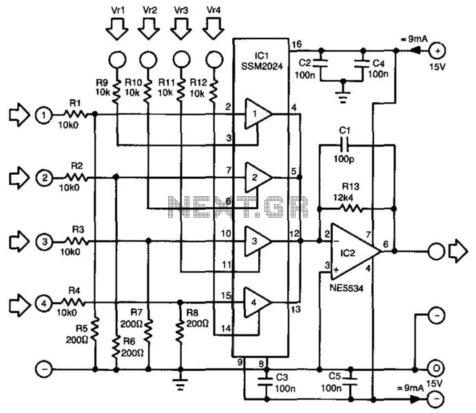
The proposed mixer is designed around four current-driven transconductance amplifiers contained in an SSM2024 from Precision Monolithics. To achieve low offset and high control rejection, the four inputs should have an impedance to earth of approximately 200 ohms. These...
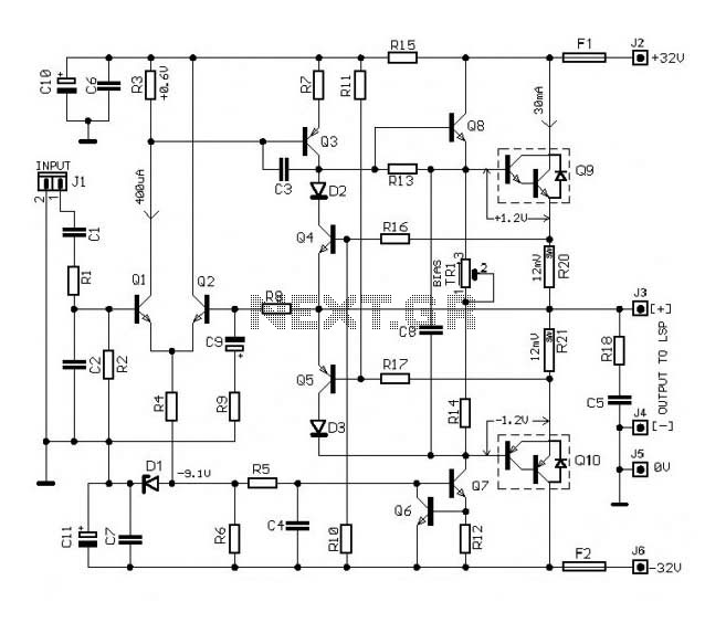
The circuit of this 30W audio amplifier produces clear audio output quality. The circuit module does not have any improvements. It utilizes a Darlington pair in the transistor configuration. The 30W audio amplifier circuit is designed to deliver high-fidelity sound...