
Dynamic noise reduction with DC volume control

The described circuit configuration incorporates two primary functions: dynamic noise reduction and volume/tone control. The dynamic noise reduction circuit is designed to minimize unwanted noise in audio signals, enhancing the overall sound quality by filtering out high-frequency interference and other extraneous sounds. This is particularly beneficial in applications where clarity and fidelity are paramount, such as in audio amplifiers and sound systems.
The DC volume control circuit allows for the adjustment of audio signal amplitude, providing users with the ability to set the desired loudness level. This is typically achieved through a variable resistor or a digital potentiometer, enabling precise control over the output signal.
The tone balance control circuit complements the volume control by allowing users to adjust the tonal quality of the audio signal. This can include adjustments to bass, midrange, and treble frequencies, enabling tailored sound profiles to suit individual preferences or specific audio environments.
Both of these circuits are strategically placed at the input stage and the discharge line of the amplifier. The input stage is critical as it is where the audio signal first enters the system, making it the ideal point for noise reduction to occur. By implementing the volume and tone control at this stage, the system can effectively manage the audio signal before it is amplified, ensuring that the output is both clean and tailored to the listener's specifications.
In summary, this circuit design provides a comprehensive solution for managing audio quality, combining noise reduction with volume and tone control to enhance the listening experience in various electronic audio applications.Dynamic noise reduction circuit and a DC volume, tone balance control circuit, which is applied to the input stage and the discharge line between the amplifier. See DC volume c ontrol circuit
Related Circuits
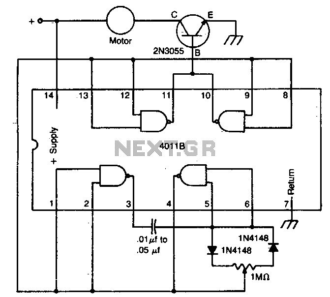
The circuit utilizes a 4011 CMOS NAND gate, a pair of diodes, and an NPN power transistor to create a variable duty-cycle DC source. By adjusting the speed control, the average voltage applied to the motor can be varied,...
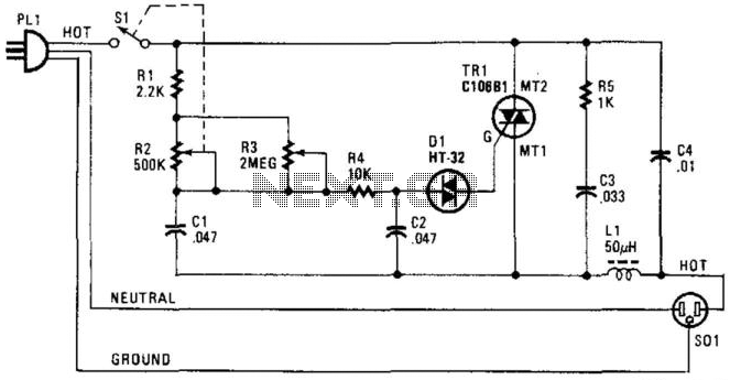
A phase-controlled triac (HT-32) circuit offers control over the effective voltage at the load. It is important to include LI and C4, as they are essential for RFI suppression. The maximum load capacity is approximately 500 W. WARNING: 120...
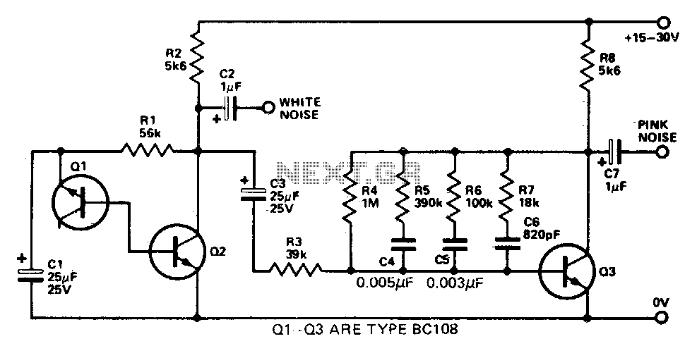
This simple circuit generates both white and pink noise. Transistor Q1 functions as a zener diode, with the base-emitter junction being reverse-biased to achieve zener breakdown at approximately 7 to 8 volts. The zener noise current from Q1 flows...
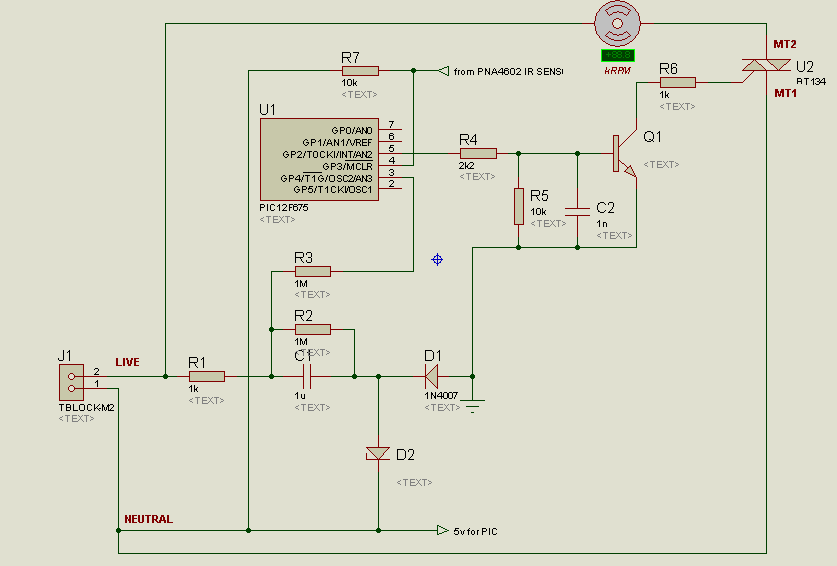
A project is underway to control the speed of an electric fan (220Vac, 60W, 5A max.) automatically using a microcontroller based on certain parameters. The circuit design for controlling the speed of an electric fan involves several key components to...
A circuit designed to extract and measure the modulated carrier signal from an infrared (IR) remote control. This circuit does not physically separate control pulses from modulation; instead, it amplifies the complete received signal, allowing the waveform to be...
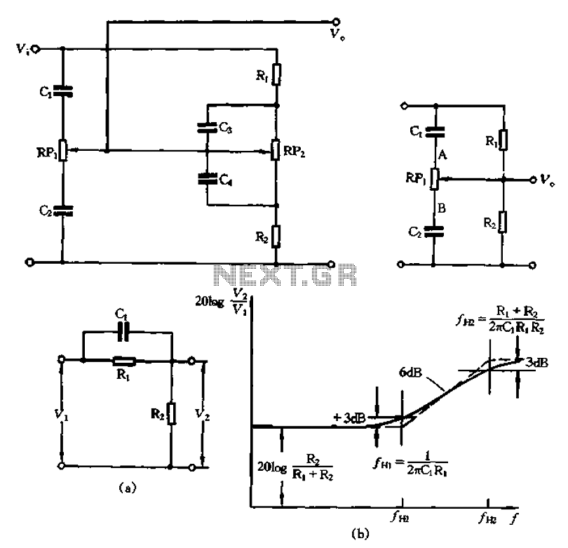
The circuit illustrated in Figure 1-560 represents a treble control potentiometer. Due to the larger capacitance values of C3 and C4 compared to C1 and C2, high-frequency signals can treat C4 as a short circuit. Consequently, the treble adjustment...