
Easy Auto power battery charging circuit

The automatic battery charging circuit operates by utilizing a voltage sensing mechanism to monitor the battery's charge level. The primary components typically include a transformer, rectifier, voltage regulator, and a microcontroller or comparator for sensing the battery voltage.
The transformer steps down the AC voltage from the mains supply to a lower AC voltage suitable for charging the battery. The rectifier, usually a bridge rectifier configuration, converts the AC voltage to DC voltage, which is necessary for charging the battery. The output of the rectifier is then filtered using capacitors to smooth out the ripples, providing a stable DC voltage.
A voltage regulator may be employed to ensure that the voltage supplied to the battery does not exceed its rated charging voltage. This is crucial for preventing damage to the battery and ensuring a safe charging process.
The microcontroller or comparator continuously monitors the battery voltage. When the battery reaches its full charge voltage, the circuit automatically disconnects the charging current, effectively shutting off the power to the charger. This feature is essential in preventing overcharging, which can lead to battery overheating, reduced lifespan, or potential hazards.
Additional features may include LED indicators to show the charging status and a fuse for overcurrent protection. The design can be tailored to accommodate various battery types, such as lead-acid, lithium-ion, or nickel-cadmium, by adjusting the charging parameters accordingly.
Overall, this automatic battery charging circuit provides a reliable and efficient solution for maintaining battery health and performance while ensuring user safety.Easy Auto power battery charging circuit Is shown as a simple automatic power battery charging circuit, the circuit can automatically power off when the battery is fully charge d, it will not overcharge phenomenon.
Related Circuits
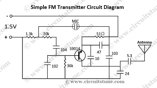
This is a simple FM transmitter circuit schematic diagram that utilizes a single transistor, S9014. The FM transmitter circuit operates by modulating an audio signal onto a carrier frequency, which is typically in the FM band. The S9014 transistor serves...
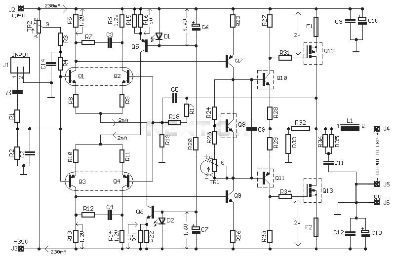
This HEXFET Audio Amplifier 65 Watts circuit diagram includes three circuit images. For a more comprehensive understanding, refer to the original post titled "HEXFET Audio Amp 65 Watts." The post not only provides circuit information but also includes a...
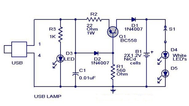
A simple USB-powered lamp designed to illuminate a desktop during power outages. The circuit operates at 5 volts sourced from a USB port. The 5V from the USB is directed through a current-limiting resistor (R2) and a transistor (Q1)....
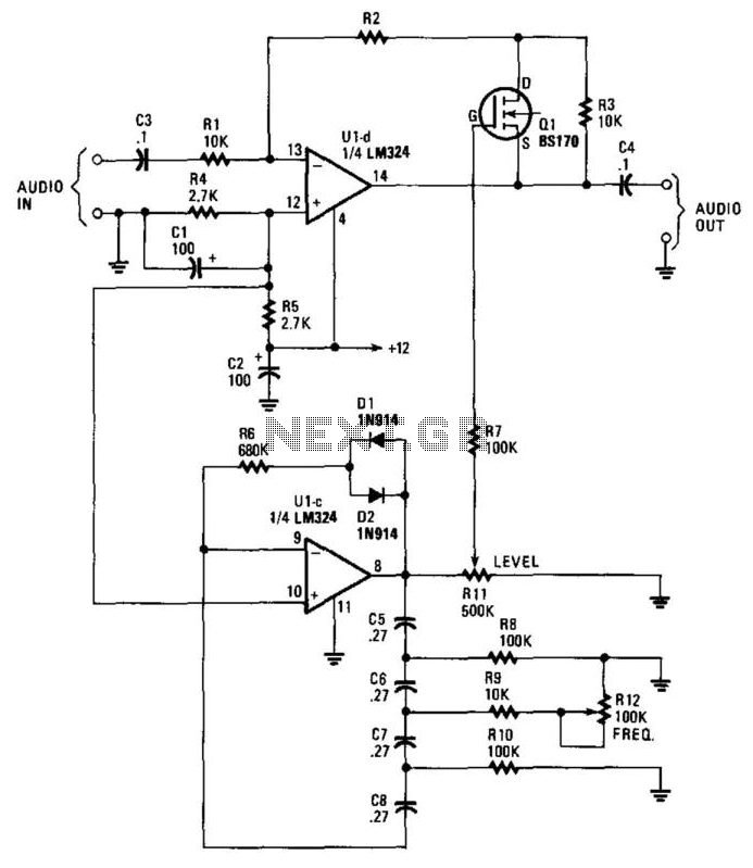
This circuit incorporates a Very Low Frequency (VLF) Amplitude Modulation (AM) component into an audio signal. This effect is commonly utilized in musical instruments. U1C, a phase-shift oscillator functioning at a few Hertz, generates a signal that modulates the...

This is a circuit design for a digital voltmeter with an LED display. It is suitable for measuring the output voltage of a DC power supply. The circuit features a 3.5-digit LED display with a negative voltage indicator and...
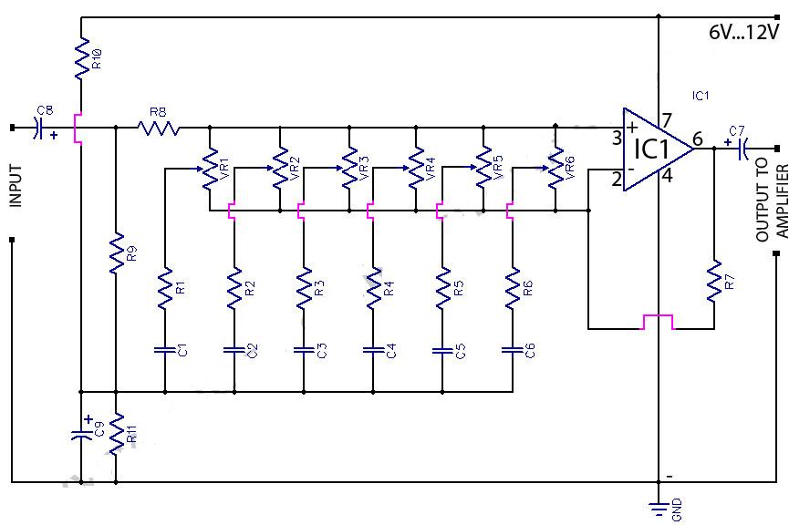
This circuit is a six-band graphic equalizer that allows modification of sound across low, mid, and high frequencies using an IC 741 operational amplifier. It enables management and mixing of frequencies and tones as desired. The audible frequency spectrum...