
economy radar detector

The radar detector circuit based on the 1458 dual op-amp is designed to detect radar signals effectively while minimizing false triggers from background noise. The first op-amp's configuration as a current-to-voltage converter is critical for converting the radar signal's current output into a usable voltage signal. This conversion allows for better signal processing and increases the sensitivity of the radar detection.
The second op-amp's buffering function is essential for isolating the signal from the first op-amp and ensuring that it can drive the piezo transducer without loading the previous stage. This buffering minimizes signal degradation and allows the transducer to produce an audible alert when a radar signal is detected.
Resistor R5 plays a vital role in setting the sensitivity of the circuit. By adjusting R5, the user can set the threshold at which the second op-amp activates, ensuring that the circuit responds only to significant radar signals rather than fluctuating background noise. This adjustment is crucial for maintaining the detector's reliability and effectiveness in various environments.
The tuning of the circuit's response through the length of the leads on capacitor C1 is an interesting aspect of the design. The specified lead length of 0.5 to 0.6 inches is optimized for typical road-radar frequencies, allowing for appropriate capacitance and inductance characteristics that influence the circuit's overall performance. By fine-tuning these leads, users can achieve a more tailored response to specific radar systems, enhancing detection capabilities.
Overall, this circuit exemplifies an efficient design for a radar detector, leveraging the dual op-amp configuration to achieve effective signal processing, sensitivity adjustment, and reliable performance in detecting radar signals.This circuit uses a 1458 dual op-amp to form a radar detector. C1 is the detector of the radar signal. The first op-amp forms a current-to-voltage converter and the second op-amp buffers the output to drive the piezo transducer. R5 sets the switching threshold of the second op-amp; normally it is adjusted so that the circuit barely triggers on bac
kground noise, then it`s backed off a bit. The response of the circuit may be tuned by adjusting the length of the leads on C1. For typical road-radar systems, the input capacitor`s leads should be about 0. 5 to 0. 6 inches long. 🔗 External reference
Related Circuits
A bright lamp flashes in synchrony with the lightning bolts, indicating the proximity and intensity of the storm. The described circuit operates as a storm warning system, utilizing a bright lamp to provide visual alerts in response to lightning activity....
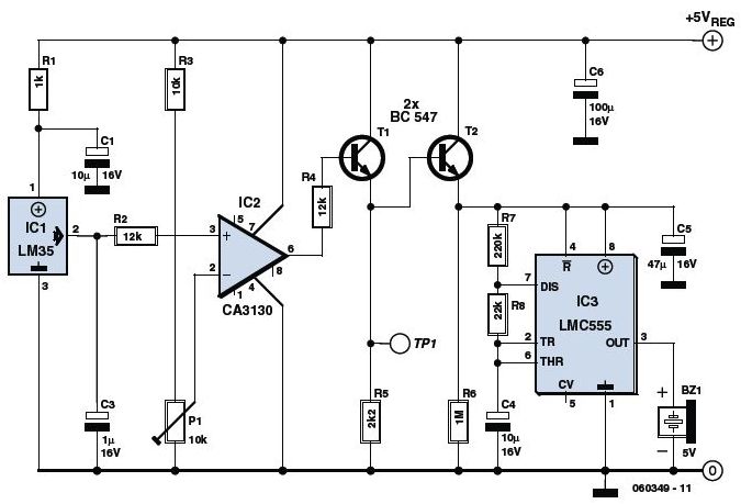
The circuit utilizes a precision integrated temperature sensor, the LM35 (IC1), which provides a linear and directly proportional output in millivolts over a temperature range of 0 to +155 degrees Celsius. This sensor can be incorporated into fire smoke...
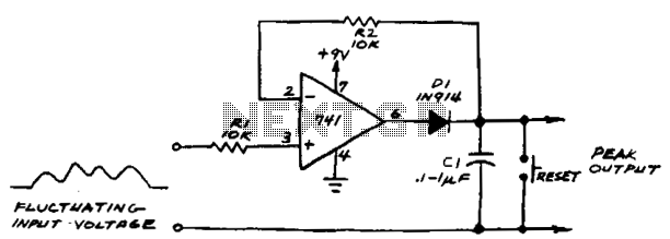
If the subsequent input voltage exceeds that stored in C1, the comparator voltage will go high and charge C1 to the new higher peak voltage. The comparator will charge C1 until the voltage across the capacitor equals the input...
This simple water detector circuit utilizes alternating voltage to prevent electrode corrosion. It is easy to construct and employs N1 as a trigger Schmitt gate to generate the AC signal. When a conductive substance, such as an aqueous solution,...
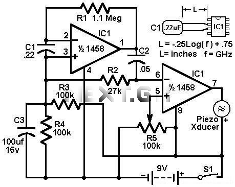
Economy radar detector circuit diagram. This circuit uses a 1458 dual op-amp to form a radar detector. C1 is the detector of the radar signal. The first op-amp forms a current-to-voltage converter, and the second op-amp buffers the output. The...
A modification to David Knight's linear detector circuit was developed to create a high-fidelity AM receiver requiring an ultra-linear AM detector. The revised circuit eliminates the meter circuit and many bypass capacitors, resulting in a design with a finite...