
Peak detector II

In this circuit, a comparator is utilized to monitor the voltage levels and control the charging of a capacitor, designated as C1. The operational principle hinges on the comparator's ability to compare the voltage across C1 with an incoming voltage signal. When the input voltage surpasses the voltage currently stored in C1, the comparator output transitions to a high state, indicating that the capacitor should be charged.
The charging process involves the comparator actively driving a control signal that connects C1 to a voltage source. This connection allows C1 to accumulate charge until the voltage across its terminals matches the level of the incoming input voltage. The charging mechanism is typically facilitated through a resistor-capacitor (RC) network, which helps regulate the rate at which C1 charges, ensuring that the voltage rise is smooth and controlled.
Once the voltage across C1 equals the input voltage, the comparator output will revert to a low state, effectively stopping the charging process. This behavior establishes a feedback loop that maintains the voltage across C1 at the same level as the input voltage, thus enabling stable operation in applications such as voltage regulation, peak detection, or signal conditioning.
The design considerations for this circuit should include the selection of appropriate values for C1 and any resistors used in conjunction with the comparator, as these components will influence the response time and stability of the circuit. Additionally, the comparator's specifications, such as its input voltage range and output drive capability, must be compatible with the intended application to ensure reliable performance. If subsequent input voltage exceeds that stored in Cl, the comparator voltage will go high and charge Cl to new higher peak voltage. The comparator will charge Cl until the voltage across the capacitor equals the input voltage.
Related Circuits

The metal detector circuit employs an LC single-tube oscillator configuration, as illustrated in Figure 8-73. In this circuit, V represents the oscillating tube, L denotes the detection coil, and C1 is the resonant capacitor. Upon activation of the power...

Attribution is required to give credit to the author or licensor of the work, as specified, without implying endorsement of the user or their use of the work. This file includes additional information, such as EXIF metadata, which is...
Listen and share music wherever you go with the mini speaker system project. This project allows for music playback in various locations such as dorms, cubicles, or the beach. It serves as an excellent introduction to circuit systems, featuring...
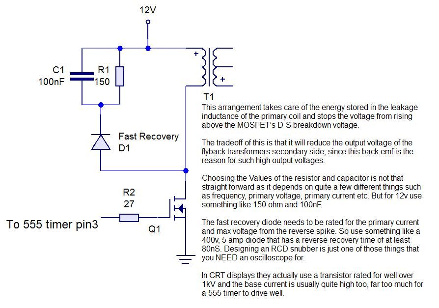
This instructable demonstrates the process of creating an audio-modulated plasma speaker using a flyback transformer salvaged from an old CRT display. The audio-modulated plasma speaker operates by utilizing a high-voltage output from a flyback transformer to create a plasma arc...
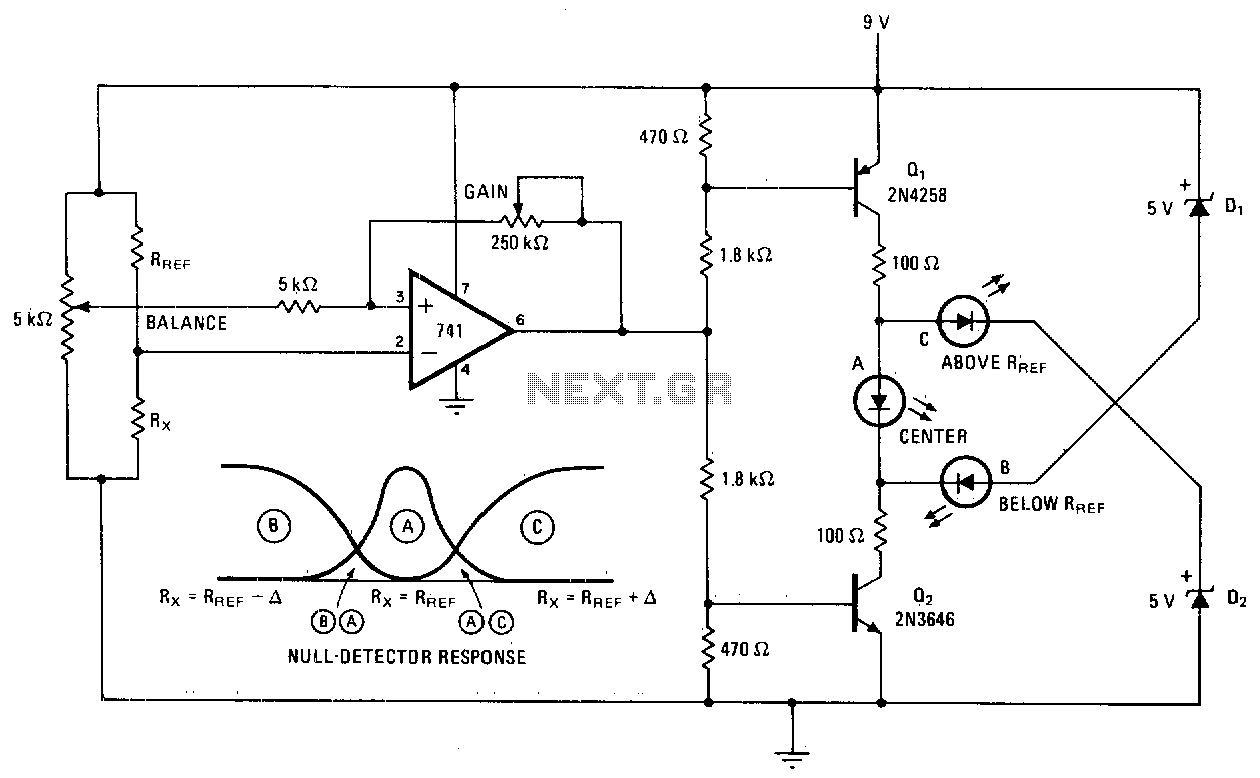
A null detector employs a basic LED readout to indicate whether the test resistor R* is below, equal to, or greater than the reference resistance Rref. When R* equals Rref, the output of the 741 operational amplifier stabilizes at...
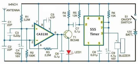
Cellular phone detector circuit schematic using common electronic parts The cellular phone detector circuit is designed to identify the presence of a cellular phone within a specified range. This circuit utilizes basic electronic components, making it accessible for hobbyists and...