
Economy radar detector

The radar detector circuit utilizing the 1458 dual op-amp is designed for efficient detection of radar signals. The circuit's architecture consists of two operational amplifiers (op-amps) integrated within the 1458 IC. The first op-amp is configured as a current-to-voltage converter, which transforms the incoming radar signal detected by capacitor C1 into a proportional voltage. This conversion is critical for accurately interpreting the radar signal strength.
The second op-amp serves as a buffer, providing isolation between the signal processing stage and the output stage, which drives the piezo transducer. This buffering action ensures that the output signal maintains integrity and does not affect the performance of the first op-amp. The piezo transducer converts the electrical signal into an audible sound, alerting users to the presence of radar signals.
Resistor R5 plays a vital role in determining the sensitivity of the circuit. By adjusting R5, the user can set the threshold at which the second op-amp activates. This threshold is typically calibrated to respond only to significant radar signals, minimizing false positives from background noise. The initial setting is usually at a point where the circuit just starts to trigger on background noise, followed by a slight reduction to ensure reliable operation.
The performance of the radar detector can also be optimized by adjusting the lead lengths of capacitor C1. The specified lead length of 0.5 to 0.6 inches is crucial for achieving the desired frequency response and sensitivity. Longer or shorter leads may alter the circuit's performance, potentially leading to unintended results.
Overall, this radar detector circuit is a practical application of operational amplifiers in signal processing, providing an effective solution for detecting radar signals in various environments. Proper calibration of component values and lead lengths is essential for maximizing the performance and reliability of the detector.This circuit uses a 1458 dual op-amp to form a radar detector. C1 is the detector of the radar signal. The first op-amp forms a current-to-voltage converter and the second op-amp buffers the output to drive the piezo transducer. R5 sets the switching threshold of the second op-amp; normally it is adjusted so that the circuit barely triggers on bac
kground noise, then it`s backed off a bit. The response of the circuit may be tuned by adjusting the length of the leads on C1. For typical road-radar systems, the input capacitor`s leads should be about 0. 5 to 0. 6 inches long. 🔗 External reference
Related Circuits

This circuit diagram represents a low-cost metal detector utilizing a single transistor circuit in conjunction with an old pocket radio. It operates as a Colpitts oscillator functioning within the medium band frequency range, with the radio tuned to the...
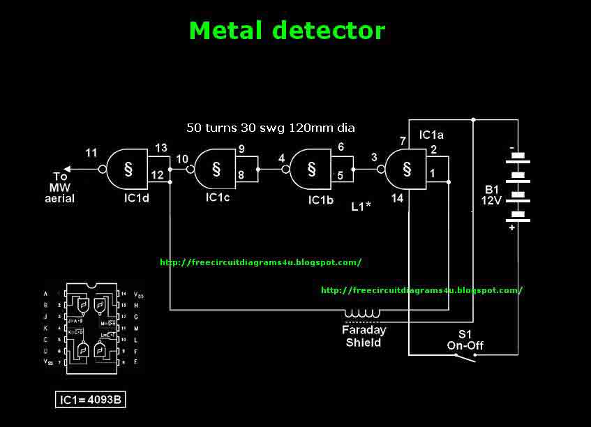
This circuit needs a Faraday shield, which is connected to 0V. To make this one wrap a tin foil around the coil and connect to 0V. Then you can use this circuit to find metal. Tune your mw radio...
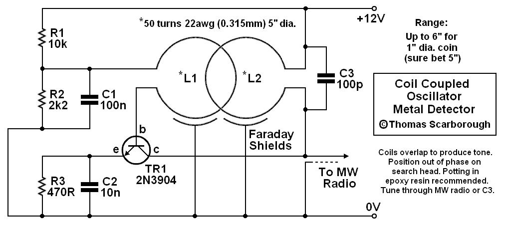
A coil-coupled operation metal detector constructed from commonly available components, utilizing a standard medium receiver as the detection unit. The coil-coupled operation metal detector functions by employing a transmitter coil and a receiver coil that are magnetically coupled. The transmitter...
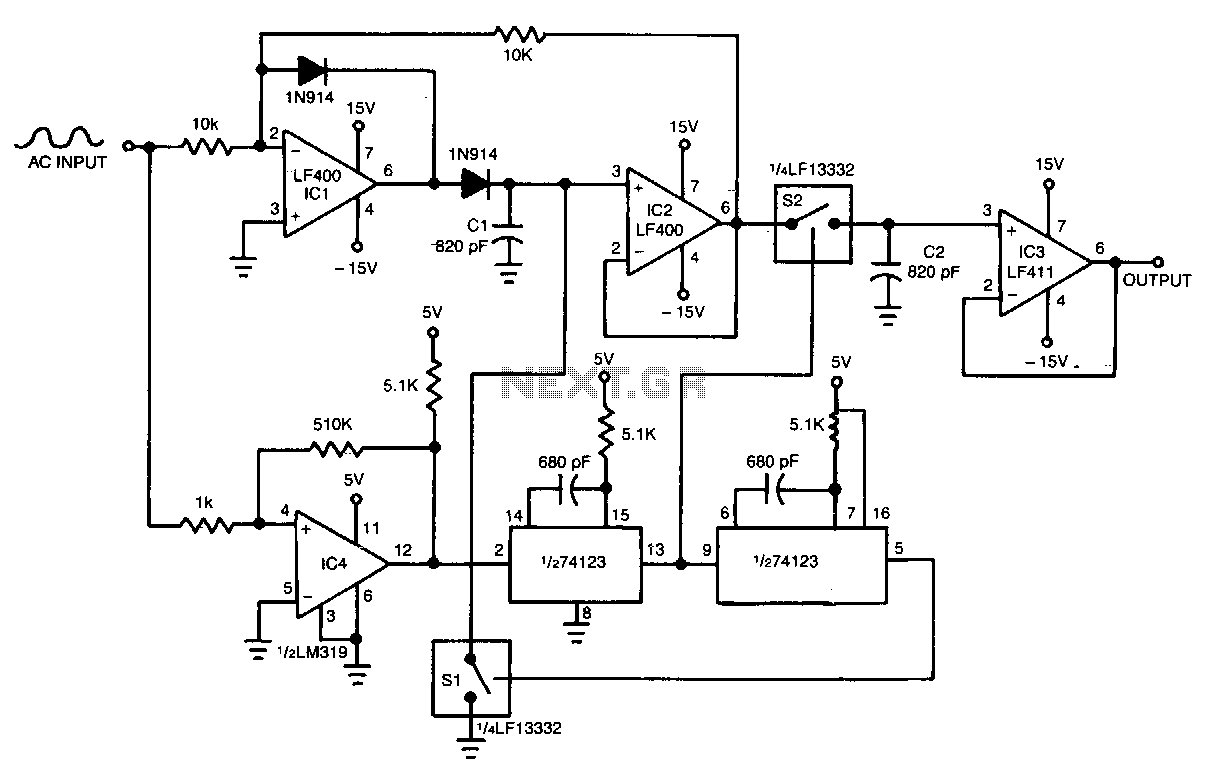
IC1 and IC2 form an inverting half-wave precision rectifier and peak detector circuit. Negative input signals that swing with peaks larger than the voltage on C1 cause this capacitor to charge to the new peak voltage. The capacitor retains...
The circuit described is a metal detector. The operation of the circuit is based on the superheterodyne principle, which is commonly used in superheterodyne receivers. The circuit utilizes two RF oscillators, both fixed at a frequency of 5.5 MHz....
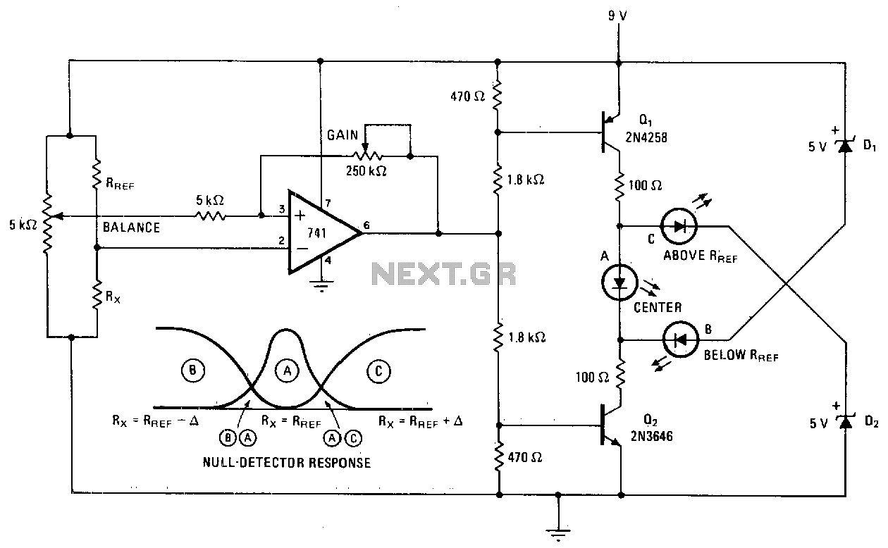
A null detector employs a basic LED readout to indicate whether the test resistor R* is below, equal to, or greater than the reference resistance Rref. When R* equals Rref, the output of the 741 operational amplifier stabilizes at...