
Absolute-Value Meter With Polarity Detector

The circuit operates by utilizing operational amplifiers (op-amps) to achieve the desired signal processing. The first stage of the circuit involves rectification, where the absolute value of the input voltage is obtained. This is typically accomplished using a precision rectifier configuration, which allows for accurate rectification of small signals without the voltage drop associated with traditional diodes.
Following the rectification stage, the circuit employs a comparator or a simple logic circuit to determine the polarity of the input voltage. This is achieved by comparing the input signal against a reference voltage, usually set to zero volts. The output of this stage indicates whether the input voltage is positive or negative, thus providing the necessary sign information.
The final output of the circuit consists of two separate signals: one representing the absolute value of the input voltage and the other indicating the polarity. This dual-output configuration can be particularly useful in applications such as analog signal processing, where both the magnitude and direction of the signal are critical for further processing or control tasks.
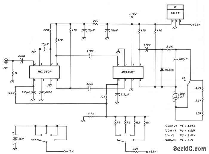
Overall, this circuit design is fundamental in various electronic applications, including signal conditioning, measurement systems, and control circuits, where precise voltage analysis is required.This circuit breaks an input voltage signal down into its components: (1) the absolute value and (2) the polarity or ‘sign (+ or ). It will handle direc.. 🔗 External reference
Related Circuits

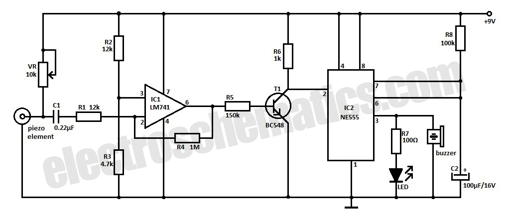
This compact mobile transmission detector is capable of sensing the presence of an active mobile phone from a distance of 1.5 meters. It can be utilized to prevent mobile phone usage in examination halls, confidential areas, and similar environments....
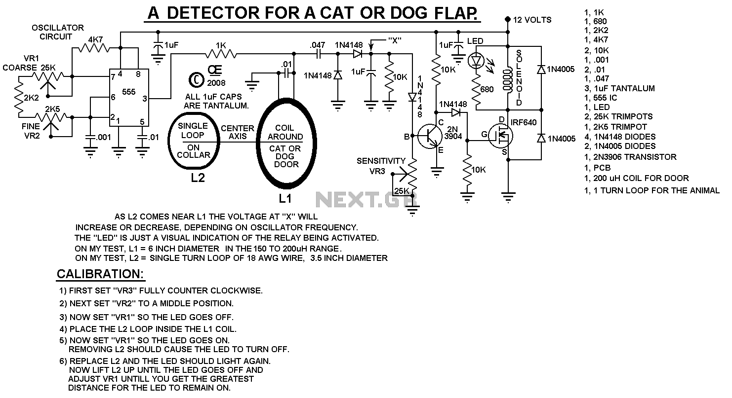
This can be used to control entry on a Cat or Dog Door. NOTE: There may be some changes and improvements coming. However, this circuit does work and you can build it as shown. The PCB shown below is...
Having found a u664b prescaler chip (Telefunken) from an old TV tuner, I decided to build a valid frequency counter using PIC16F84. The prescaler I use is able to divide by 64 every frequency from 30 to 1300 MHz....
This circuit will automatically switch on several mains-powered "slave" loads when a "master" load is turned on. For example, it will switch on the amplifier and CD player in a stereo system when the receiver is turned on. It...
This is an ultra-sensitive earthquake detector circuit capable of sensing seismic vibrations. It can be utilized to detect vibrations in the Earth. The ultra-sensitive earthquake detector circuit is designed to respond to minute seismic vibrations, making it an essential tool...
This schematic illustrates a peak-reading diode voltmeter that is powered by two amplification stages. A 100 µF capacitor is utilized to create a substantial time constant, which ensures effective damping of the meter. The restricted differential output voltage, combined...