
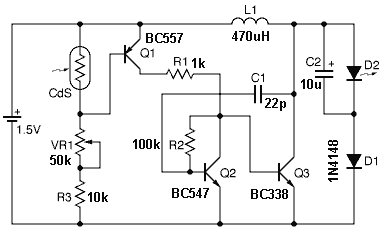
Photo detector using LED

The described circuit utilizes a light-dependent voltage generation mechanism through the photo-voltaic effect exhibited by an LED. When exposed to light, the LED generates a small voltage, which is then buffered using a junction field-effect transistor (JFET). The purpose of the JFET in this configuration is to provide high input impedance, minimizing the load on the LED and ensuring that the voltage produced is not significantly affected by the circuit's input characteristics.
The buffered voltage from the JFET is fed into the inverting input of an operational amplifier (op-amp). The op-amp is configured with a gain of approximately 20, which amplifies the input voltage signal from the LED. This configuration allows for a significant output voltage swing in response to changes in ambient light levels. Specifically, the output voltage can vary from around 7 volts in low-light conditions (darkness) to approximately 2 volts in bright light conditions, demonstrating a dynamic range that can be effectively utilized in light-sensing applications.
A 100K potentiometer is incorporated into the circuit to adjust the sensitivity and output voltage levels. By varying the resistance of the potentiometer, the user can calibrate the circuit to achieve the desired output range, thereby allowing for flexibility in different lighting environments. This feature is particularly useful in applications such as automatic lighting systems or light-sensitive alarms, where precise voltage output corresponding to light levels is critical.
Overall, this circuit design showcases an efficient method of converting light intensity into a measurable voltage output, utilizing readily available components such as an LED, JFET, and op-amp, making it a practical solution for various electronic applications.Here's a circuit that takes advantage of the photo-voltaic voltage of an ordinary LED. The LED voltage is buffered by a junction FET transistor and then applied to the inverting input of an op-amp with a gain of about 20. This produces a change of about 5 volts at the output from darkness to bright light. The 100K potentiometer can be set so that the output is around 7 volts in darkness and falls to about 2 volts in bright light. 🔗 External reference
Related Circuits
In various industrial processes, it is essential to rotate a DC (or AC) motor both forward and reverse for a specified duration. Initially, the motor rotates forward (clockwise) for a certain period (approximately 2 to 3 minutes), then stops...

This compact receiver is slightly larger than an AA battery. It is powered by two LR44 button cells, which are relatively costly and may not have a long lifespan. There is an intention to search for LR44 batteries at...

This circuit diagram for a 12V inverter is simple to construct and utilizes inexpensive components that many electronics hobbyists may already possess. While it is feasible to create a more powerful circuit, the complexity arises from managing the significant...
In this fire alarm circuit, a thermistor functions as the heat sensor. As the temperature rises, its resistance diminishes, and conversely, when the temperature falls, its resistance increases. At standard temperature, the resistance of the thermistor (TH1) is approximately...
It is essential to draw a circuit using a layout and conventions that are universally recognized. In electronic circuit design, adherence to standardized symbols and layout conventions is crucial for effective communication among engineers and technicians. A well-drawn schematic diagram...
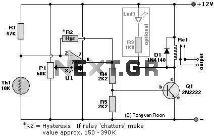
The following page outlines detail information on how to step by step design a Simple Heat Sensor Circuit. This circuit design utilized LM741 as the operational amplifier. More: Circuit Parts/Components List: Re1 = 12V relay R1 = 47K R2...