
1995 Toyota Supra Electrical

The 1995 Toyota Supra electrical circuit diagram provides a comprehensive overview of the vehicle's electrical system. It details the flow of electricity from the battery to various components, illustrating how power is distributed throughout the vehicle. The diagram typically includes the battery, alternator, starter motor, fuses, relays, and various sensors and actuators.
Key features of the diagram include the representation of the power source, which is the battery, and its connections to the alternator, responsible for charging the battery while the engine is running. The starter motor is also depicted, showing how it interacts with the ignition system to initiate engine operation.
Fuses and relays are included to protect circuits and manage the flow of electricity to components such as headlights, taillights, and interior lighting. Additionally, the diagram may highlight critical sensors that monitor engine performance and vehicle systems, such as the oxygen sensors, throttle position sensor, and various control modules.
The schematic is essential for troubleshooting electrical issues, allowing technicians to trace the electrical pathways and identify potential faults or failures within the system. Understanding the layout and function of each component is crucial for effective maintenance and repair of the vehicle's electrical system.Description: 1995 Toyota Supra Electrical Circuit Diagram. Features: shown from the point where the power source is received from the battery as far as each .. 🔗 External reference
Related Circuits
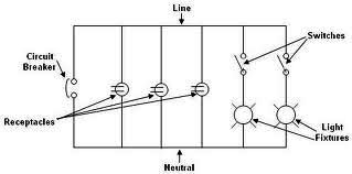
Each component of the circuit is represented in a simple block form with corresponding labels for identification, using no special symbols or language. The interconnections between these components are depicted by solid lines. The block diagrams can be read...
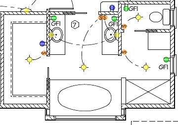
The following circuit illustrates the installation of a bathroom electrical wiring circuit diagram. Features include safety, energy savings, and enhancement of home functionality. This circuit diagram provides a comprehensive overview of the electrical wiring necessary for a bathroom installation. It...
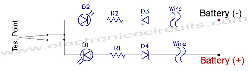
12V Vehicle Electrical Wiring Tester Circuit. This tester is useful for checking vehicle electrical circuits. Two LEDs indicate whether the circuit is live or not. The 12V vehicle electrical wiring tester circuit is designed to provide a simple yet effective...
Control electrical appliances using a PC. This circuit utilizes the printer port of a PC for control applications through software and some interface hardware. The interface circuit is included. The described circuit leverages the parallel printer port (also known as...
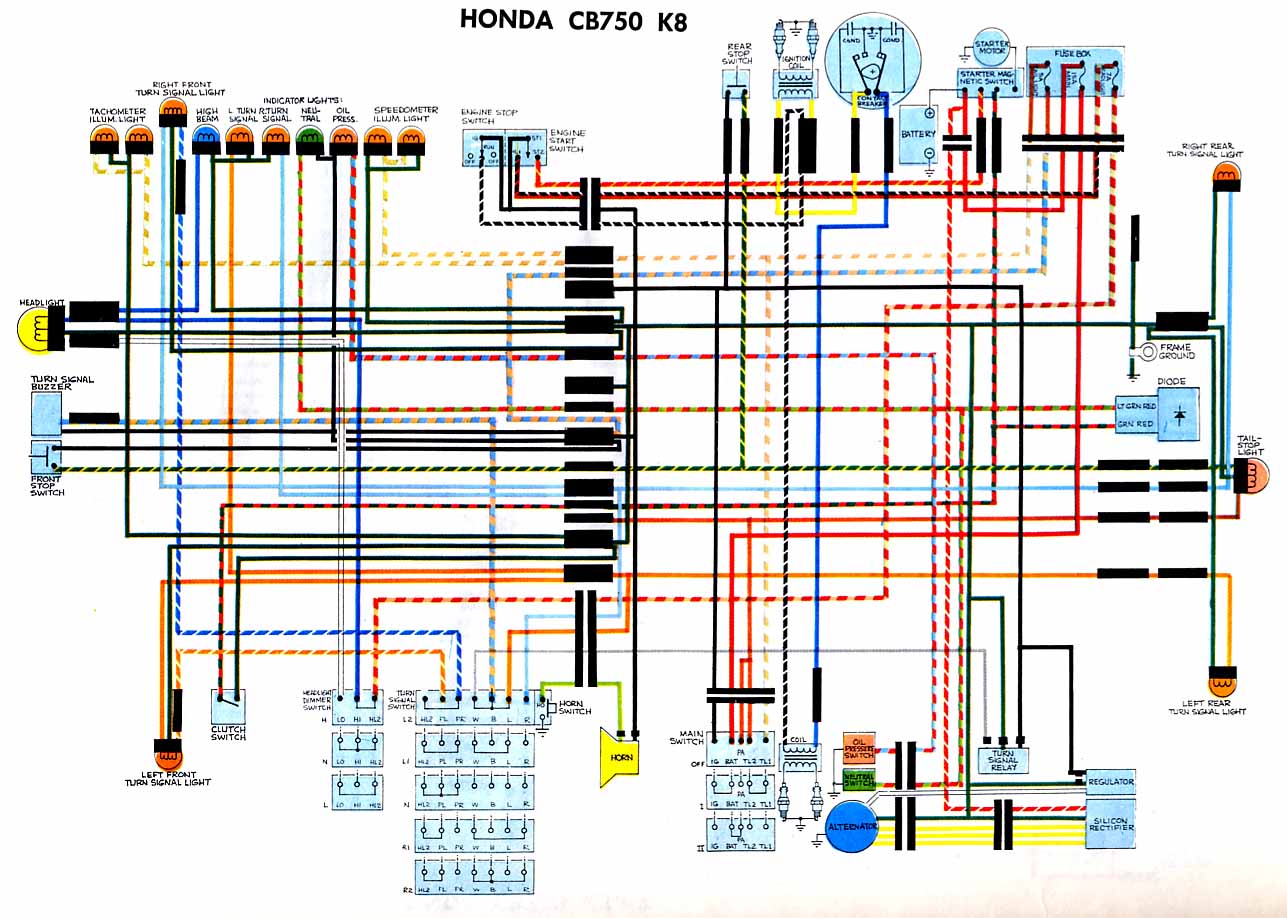
The following circuit illustrates the electrical circuit diagram for the Honda CB750 motorcycle. Features include a turn signal relay, oil pressure switch, and neutral switch. The Honda CB750 electrical circuit diagram is designed to facilitate the understanding and troubleshooting of...
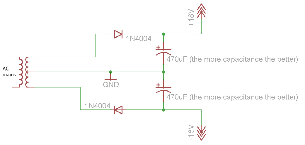
Afroman explains the fundamentals of transformer operation, where to purchase step-down mains transformers, and how to safely wire one to mains voltages. The discussion includes both European and North American wiring standards. The presentation concludes with a brief example...