
Electric Wiring Diagram For PMW Using Inverter Gates

The LMH6552 is a high-speed, low-distortion amplifier designed for differential signal processing. It features a wide bandwidth, making it suitable for applications that require precise signal integrity over a range of frequencies. The device operates from a single or dual power supply, which allows for flexibility in circuit design.
In this configuration, the LMH6552 amplifies incoming differential signals while minimizing distortion, ensuring that the output maintains fidelity to the original input. The resistors used in the circuit serve multiple purposes, including setting the gain of the amplifier and establishing the input and output impedance levels to match the requirements of subsequent stages in the signal chain.
For optimal performance, careful selection of resistor values is critical as they influence the overall gain, bandwidth, and stability of the amplifier circuit. Additionally, proper layout considerations must be taken into account to minimize noise and interference, which can degrade the quality of the amplified signal. This circuit is particularly useful in applications such as audio processing, data acquisition systems, and communication systems where maintaining signal quality is paramount.Function: used to give balanced little distortion amplification and level shifting to wide bandwidth differential signals. Component: LMH6552 IC, Resistor, .. 🔗 External reference
Related Circuits
The circuit utilizes an integrated circuit (IC) type multivibrator as the oscillator for alternating current, operating at approximately 60 Hz. The 7400 IC is employed for this purpose, although the 7404 IC can also be used. The oscillator signal...
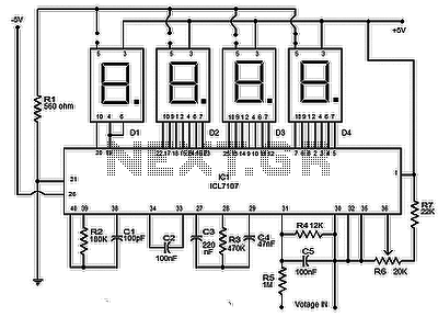
The circuit presented is a highly effective and precise digital voltmeter with an LED display utilizing the ICL7107 from Intersil. The ICL7107 is a high-performance, low-power, 3.5-digit analog-to-digital converter (ADC). This integrated circuit (IC) incorporates internal components such as...
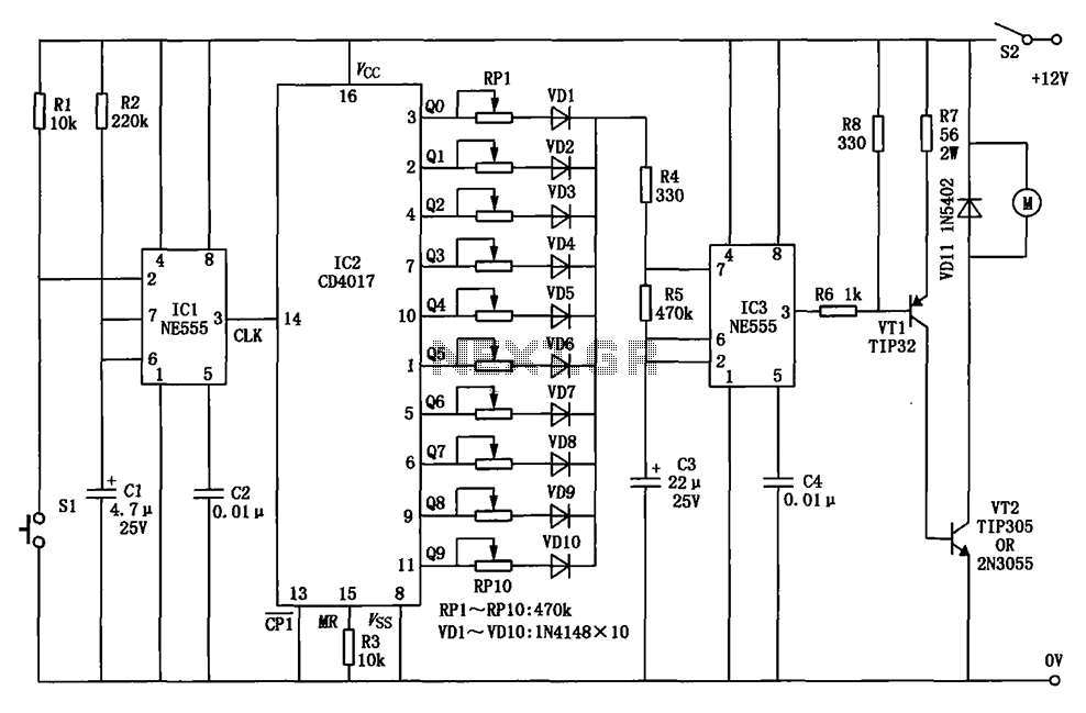
This example describes the use of HS101 and HS201 radio transmitter and receiver modules to control rotating color lights, functioning as a multi-channel radio remote control device suitable for small dance floors or home use. Users positioned at any...
This is a microphone preamplifier designed for compatibility with a SoundBlaster AWE 64 sound card. It is also suitable for any compatible tag or PC audio input that provides a 5 Volt supply through a 2.2kΩ current-limiting resistor located...
The circuit for a car wiper speed controller allows for adjustable wiper speed, ranging from one to ten cycles per second. This feature enables flexibility in operation and contributes to energy efficiency. The car wiper speed controller circuit typically employs...
The capability to control lights and fans wirelessly has transitioned from an expensive luxury to widely accessible consumer solutions. Nevertheless, creating a custom solution remains an engaging project for hobbyists and tinkerers. RobotGrrl has developed user-friendly libraries aimed at...