
Electronic Candle Blow Out

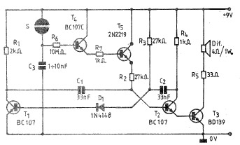
The circuit described is a simple LED control system activated by a puff of air, utilizing basic electronic components. The primary components include an electret microphone, two transistors (Q2 and Q3), a push button switch (P1), and an LED or bulb as the output indicator.
When the push button switch P1 is pressed, it triggers the base of the first transistor (Q2). This action allows current to flow from the collector to the emitter of Q2, turning it on. Q2, in turn, drives the second transistor (Q3), which is configured as a self-latching switch. This configuration means that once Q2 is activated, it keeps Q3 turned on even after the button is released. As a result, the LED or bulb connected to the output remains illuminated until the circuit is interrupted.
The electret microphone is positioned to detect a puff of air, which generates a small voltage signal when sound waves from the puff are received. This signal is amplified by the circuit, providing enough gain to turn off the transistors and thus extinguish the LED or bulb. The design effectively creates a simple interface that allows for an interactive lighting effect, making it suitable for decorative applications during festive seasons or theatrical performances.
The circuit can be assembled on a breadboard or designed into a PCB for more permanent installations. Proper power supply considerations must be made, ensuring that the voltage and current ratings for the components are adhered to, particularly for the LED or bulb, to avoid damage. Additionally, the electret microphone should be selected based on sensitivity to ensure it can adequately detect the puff of air from a reasonable distance.This design was developed by request of a correspondent having made a sort of LED candle and needing to switch off the LED with a puff. This simple, easy to build gadget can be useful as a prop for Halloween and Christmas season, shows and the like.
Q2 & Q3 form a self-latching pair that start operating when P1 is pushed: in this way the LED (or bulb) will illuminate steadily. When someone emits a strong puff in the vicinity of the small electret microphone, the resulting signal will be greatly a
🔗 External reference
Related Circuits
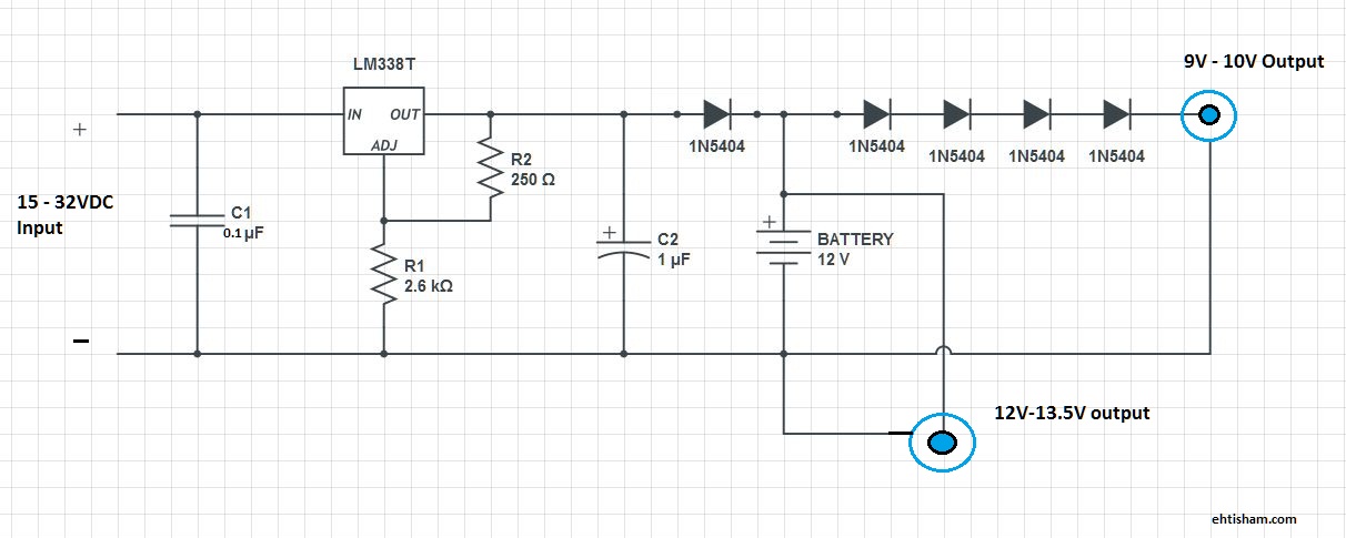
This is a basic solution that functions effectively, allowing for the powering of DSL or Wi-Fi routers for extended periods, as well as any other devices compatible with 9V or 12V. This setup ensures continuous internet access for laptops...
If the light in a seldom-used room, such as a loft, is forgotten and left on, it can remain illuminated for extended periods, leading to significant electricity costs. To address this issue, electronics enthusiasts can design a simple circuit...
A simple and practical electronic bell circuit can be constructed using the provided schematic diagram. This circuit can function as a doorbell or an alarm system. It utilizes only a few transistors along with several common components. The circuit...

The term "pentester" refers to a penetration tester, individuals who assess security vulnerabilities. Many high-end hotels globally depend on keycard locks for securing hotel rooms. However, recent incidents of theft have shown that these locks may not be as...
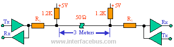
The IEEE-1284 bus specifies a parallel printer bus with data transfer speeds exceeding 1 MBps. It defines a point-to-point asynchronous bi-directional interface. Devices can be either 1284 compatible (older parallel port devices) or 1284 compliant. The maximum recommended length...

The MSK4204RH is a radiation-hardened complete H-Bridge microcircuit designed for use in DC brushed motor control applications or Class D switch-mode amplification in space or other harsh operating environments. The internal components have been selected to withstand a total...