
Electronic Cricket Match Game

The electronic cricket circuit is designed to engage children in a playful and interactive manner, allowing them to simulate cricket matches while learning basic electronic principles. The astable multivibrator configuration of IC1 generates a continuous stream of square wave pulses at a frequency determined by the values of R1, R2, and C1. This rapid oscillation is essential for creating a dynamic visual experience through the LEDs.
The CD4017 decade counter, as IC2, is particularly well-suited for this application due to its ability to count and provide multiple outputs in a sequential manner. As each pulse from IC1 triggers the counter, it activates the LEDs in a specific order, providing feedback on the simulated cricket match's status. The use of a reset pin allows the circuit to return to its initial state, enabling repeated play without manual intervention.
The push switch S1 serves as the primary control interface for the user, initiating the sequence of LED activation. The inclusion of resistor R3 is crucial for ensuring the stability of the circuit during standby, thereby preventing erroneous LED indications when the circuit is not actively engaged in play.
In summary, this electronic cricket circuit not only serves as a fun toy for children but also introduces them to fundamental concepts of electronics, such as oscillation, counting, and circuit control, all while fostering an engaging play environment. Each LED's function is clearly defined, allowing for easy understanding and interaction during gameplay.This electronic cricket is a present for Kids. This simple battery powered circuit can be used to play Cricket Match with your friends. Each LED in the circuit indicates various status of the cricket match like Sixer, Run out, Catch etc. The Circuit uses two ICs, one in the Astable mode and the second in the display driver mode. IC1 is wired as an Astable Multivibrator with the timing elements R1, R2 and C1. With the shown values of these components very fast output pulses are generated from the Astable. Output from IC1 passes into the input of IC2 which is the popular Johnson Decade counter CD4017. It has 10 outputs. Of these 8 outputs are used. Output 9 ( pin9) is tied to the reset pin 15 to repeat the cycle. When the input pin 14 of IC2 gets low to high pluses, its output turns high one by one. Resistor R3 keeps the input of IC2 low in stand by state to avoid false indications. When the Push Switch S1 is pressed momentarily, the Astable operates and all the LEDs run very fast sequentially. When S1 is released, any one of the LED stands lit which indicates the status of the match. For example, if LED D7 remains lit, it indicates Sixer and if LED 8 remains lit, it indicates Catch out.
Label each LED for its status as shown in the diagram. Pressing of S1 simulates Bowling and Running LEDs indicates running of Batsman. 🔗 External reference
Related Circuits
You can play this game alone or with your friends. The circuit comprises a timer IC, two decade counters and a display driver along with a 7-segment display. The game is simple. As stated above, it is a scoring...
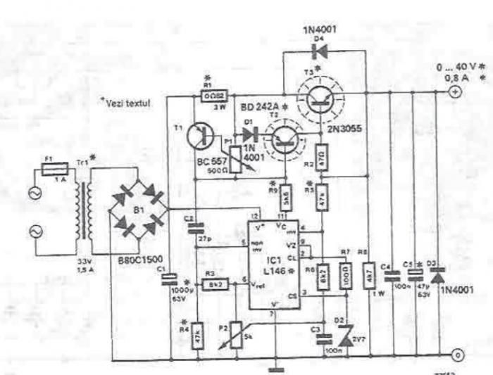
An adjustable laboratory power supply capable of providing an output voltage range from 0 to 60 volts can be constructed using the provided circuit diagram. This power supply can utilize the LM723 chip for lower voltage applications or, for...
The IC1 is a 555 timer IC configured for astable operation, generating clock pulses that are fed to IC2 through a 10K resistor. IC2 is a 10-stage counter, with output 6 (pin 5) connected to RESET (pin 15), resulting...
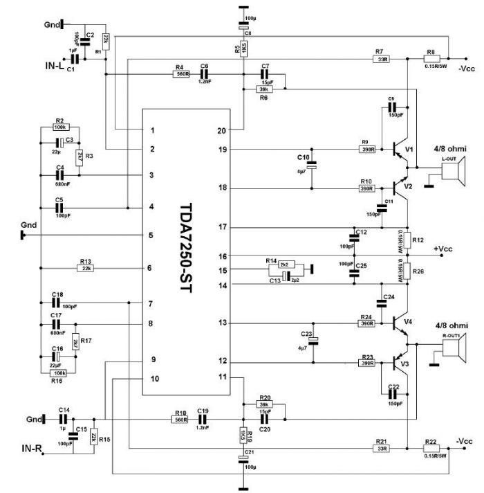
The TDA7250 audio driver, manufactured by SGS Thomson, can be utilized to design a straightforward high-power audio amplifier project with minimal external components. This audio amplifier can operate with either a 4-ohm or an 8-ohm load, delivering a maximum...

This USB to Serial RS232 adapter is highly beneficial in scenarios where a device with RS232 needs to be connected to a computer lacking an RS232 port but equipped with a USB port. Utilizing the FT232BM chip produced by...

This keyer utilizes skin conductivity to emulate the traditional mechanical CW bug keyer. When the dit paddle is activated, the bias on the inverter, IC1-a, is routed to ground, resulting in a logic high output. This triggers oscillator sections...