
Electronic Dice circuit

The circuit utilizes a 555 timer IC (IC1) configured in astable mode to produce continuous square wave pulses. This configuration allows for the generation of a clock signal, which is essential for driving the subsequent counter circuit. The clock pulses are transmitted to a 10-stage binary counter (IC2), which is configured to count from 0 to 5 by utilizing only the first six outputs.
The connection of output 6 (pin 5) to the RESET pin (pin 15) of the counter ensures that the counting sequence resets after reaching the count of 5, thereby limiting the counter's operation to a six-state sequence. The arrangement of six LEDs into three pairs allows for a visual representation of the counter's output, where each pair of LEDs corresponds to a specific count. To achieve this, four transistors are employed to control the LEDs based on the counter's outputs. The use of diodes in the circuit prevents any potential short circuits that could arise when multiple outputs drive a single transistor.
Pin 13 (INHIBIT) of IC2 plays a crucial role in controlling the operation of the counter. By connecting this pin to a positive voltage through a 100K resistor, the counter is disabled and will not advance. The introduction of a momentary pushbutton switch (S1) allows the user to connect pin 13 to ground, effectively enabling the counter to start counting. This feature simulates the action of throwing a dice, providing a random output based on the counter's state.
Powering the circuit can be achieved using a 9V battery or an external power supply capable of delivering between 9V and 12V. This flexibility in power supply options ensures that the circuit can be easily integrated into various applications. The LEDs, designated as D7 to D15, serve as visual indicators, illuminating in accordance with the output of the counter to represent the values typically associated with a dice roll. The overall design of the circuit is straightforward, making it an excellent project for demonstrating fundamental electronic principles and components.The IC1 is a 555 timer IC is connected for, Astable operation the clock pulses are fed to the IC2 via the 10K resistor. The IC2 is a 10 stage counter, output 6 (pin 5) is connected to RESET (pin 15), thus giving us a 6 stage counter, outputs 0 to 5.
The 6 of the LEDs are connected as 3 pairs, thus requiring 4 different signals, these signals come from the 4 transistors, which in turn are connected to the necessary outputs of the IC2. Where a transistor is operated from more than one output, diodes are used to avoid a short circuit situation between outputs. Pin 13 of the IC2 (INHIBIT) is connected to +ve via a 100K resistor to stop the counter from advancing, however pressing the S1 [START] button will connect pin 13 to 0V line and allow the counter to advance, hence, throwing the dice.
The circuit supply can use a 9V battery or external pack 9 until 12V. The D7 until D15 LED ’s connected as Fig. 2 to make a dice. 🔗 External reference
Related Circuits
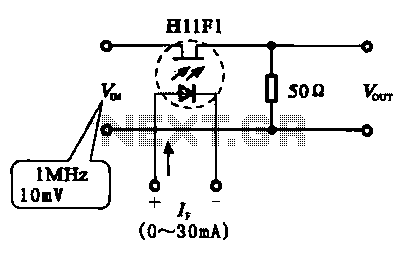
A phototransistor, also referred to as a photosensitive transistor, is primarily utilized as a photosensitive device. It is characterized by its ability to adjust impedance in relation to the intensity of incoming light, similar to that of photosensitive resistors...
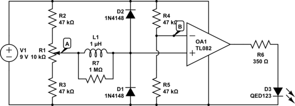
The circuit above is a canonical AC coupled common emitter amplifier, which is typically used as a linear amplifier rather than a switch that activates when the input exceeds a certain level. The AC coupled common emitter amplifier is...
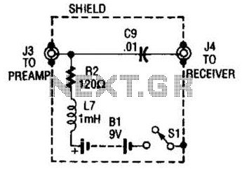
The purpose of the receiver/interface circuit is to pass RF to the receiver through capacitor C9, while adding DC power to the feedline through resistor R2 and RF choke L7. The receiver/interface circuit is designed to facilitate the transmission of...
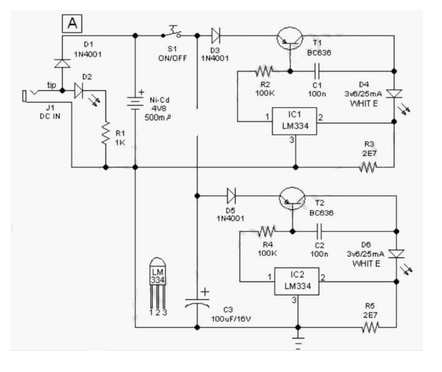
This easy-to-construct "Handy Pen Torch" electronic circuit has a low component count and utilizes two power white LEDs for lighting. It operates on a low voltage supply of 4.8V DC. The Handy Pen Torch circuit is designed to provide a...
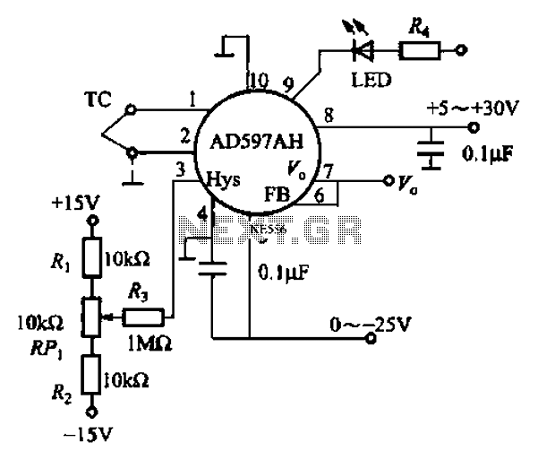
An automatic electric furnace temperature controller is illustrated. The closed circuit consists of a temperature detection output control loop; as the temperature increases, the output voltage rises until it reaches a preset temperature value, at which point the output...
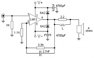
Almost all audio power amplifiers utilize integrated circuit amplifiers, such as the M12CLK, which is a power operational amplifier. This amplifier allows for an output stage that operates at an impedance of 2 ohms and provides a power gain...