
USB to Serial RS232 adapter circuit design electronic project

This USB to Serial RS232 adapter circuit primarily employs the FT232BM chip, which serves as the central component facilitating the conversion from USB to RS232. The FT232BM chip incorporates a USB controller and a serial UART interface, making it ideal for applications requiring communication between modern USB-equipped devices and older RS232 peripherals.
The circuit design typically includes the FT232BM chip, a few passive components such as resistors and capacitors, and connectors for USB and RS232 interfaces. The USB connector interfaces directly with the computer, while the RS232 connector connects to the target device. The FT232BM chip's two configurable I/O channels allow for flexible communication configurations, enabling the user to set up the parameters according to the specific requirements of the connected RS232 device.
The integrated power-on reset (POR) circuit ensures that the FT232BM chip initializes correctly upon power-up, preventing erratic behavior. Additionally, the integrated RCCLK circuit provides a clock signal necessary for synchronous communication, while the level converter facilitates proper voltage level translation between the USB and RS232 standards, which typically operate at different voltage levels.
Support for isochronous USB transfers enables the adapter to handle real-time data streams effectively, making it suitable for applications that require consistent data flow. The wake-up signal pin on each channel allows the connected RS232 device to be activated from a low-power state, ensuring efficient power management.
The low suspend current feature is particularly advantageous for battery-powered devices, as it minimizes power consumption when the adapter is not in active use. The programmable receive buffer timeout allows for customization of data handling, ensuring that data is processed efficiently without unnecessary delays.
The USB 2.0 compatibility ensures high-speed data transfer rates, which is essential for modern applications. The extended EEPROM support enables additional configuration options and firmware updates, enhancing the versatility of the adapter in various applications.
In summary, this USB to Serial RS232 adapter, built around the FT232BM chip, provides a robust solution for connecting RS232 devices to USB-equipped computers, featuring a range of functionalities that enhance its performance and adaptability in diverse electronic applications.This USB to Serial RS232 adapter is very useful in many situations we need to connect a device with RS232 to a computer without RS232 port, but with USB port. Using FT232BM chip manufactured by Future Technology Devices International we can make a very simple USB to Serial RS232 adapter using few external components.
FT232 driver main features are : Two Individually Configurable IO Channels, Integrated Power-On Reset (POR) circuit, Integrated RCCLK circuit, Integrated level converter on UART / FIFO interface and control signals, Support for Isochronous USB Transfers, Wake Up Signal Pin on each channel, Low suspend current, Programmable Receive Buffer Timeout, USB 2. 0, Extended EEPROM Support and many other. 🔗 External reference
Related Circuits
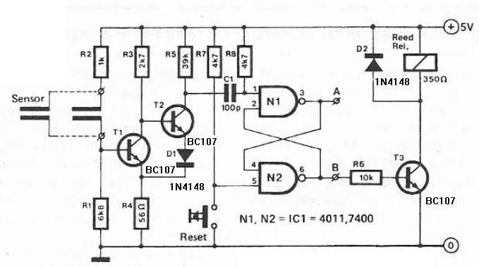
Humidity detector circuit electronic project using common electronic parts The humidity detector circuit is a project designed to measure and indicate the level of humidity in the environment. This circuit utilizes commonly available electronic components, making it accessible for hobbyists...
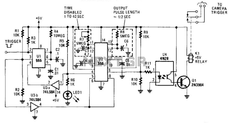
This circuit is designed to activate a camera shutter. Grounding pin 2 of U1 causes pin 4 of U1 to go high, which triggers both timers of the dual timer U1. One output maintains the reset (pin 4) of...
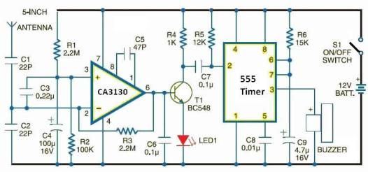
This electronic schematic can be used to design a simple cellular phone detector circuit capable of sensing the presence of an activated mobile phone from a distance of approximately 1.5 meters. The C3 capacitor should have lead lengths of...

Design a low-cost 4- to 20-mA receiver circuit for control loops using an analog-to-digital converter (ADC). The design of a low-cost 4- to 20-mA receiver circuit is essential in industrial applications for monitoring and controlling processes. This current loop standard...
Function: to trigger a device or operate in free-running mode. Components: Battery, Charger, Battery Connector, Capacitor, Integrated Circuit (IC), Resistor VR1-10K, Resistor R1-1K, Resistor R2. The described circuit functions either to trigger a connected device or to operate in a...
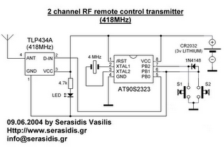
The following circuit illustrates a 3V power supply designed for an RF remote control circuit. This circuit is based on the AT90S2323 integrated circuit (IC). Features include a data rate of 2400 bps. The 3V power supply circuit for the...