
Electronic Dice

The circuit involves a switch SI that serves as an input trigger for the operation of the counter U2. Upon pressing the switch, the oscillator circuit formed by U1A and U1B generates a clock signal that drives the counter U2. The counter U2 is capable of counting from 0 to 6, and the current count value is presented on the display unit DISP1, which is likely a seven-segment display or similar output device.
The components R1 and C1 play a crucial role in setting the timing characteristics of the oscillator. The resistor R1, in conjunction with the capacitor C1, defines the frequency of oscillation, which directly influences the speed at which the counter increments. A faster count rate is essential for achieving a random count, as it minimizes the likelihood of repeated values appearing in quick succession.
In practical applications, the values of R1 and C1 should be selected to ensure that the frequency of the oscillator is high enough to provide a smooth and continuous count without noticeable gaps. This can be achieved by using a combination of standard resistor and capacitor values, calculated based on the desired frequency of operation. Additionally, the design may incorporate debouncing techniques for the switch SI to prevent false triggering due to mechanical bounce when the switch is pressed.
The output from the counter U2 can be further utilized in various applications, such as in games, random number generation, or other electronic systems requiring a non-repetitive counting mechanism. The overall design emphasizes reliability, speed, and clarity in the output display to ensure effective user interaction. When SI is pressed, counter U2 is driven by oscillator U1A/U1B and the count (0 through 6) is read on DISP1. Rl and CI dete rmine the count rate, which should be fast enough to ensure a "random" count.
Related Circuits

Automatic electronic refrigerator deodorant sterilization circuit The automatic electronic refrigerator deodorant sterilization circuit is designed to eliminate odors and sterilize the interior of a refrigerator. This circuit typically employs a combination of sensors, microcontrollers, and sterilization techniques to achieve effective...
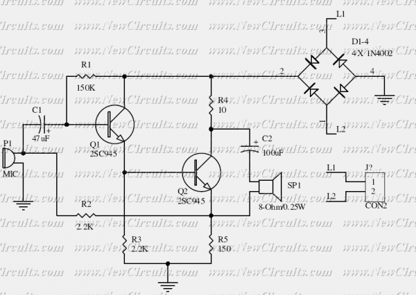
This is the basis of electronics telephone sets. You can use it to replace the talking circuit of an old telephone set with new design, better noise rejection and reliability one. Also you can use it to build a...
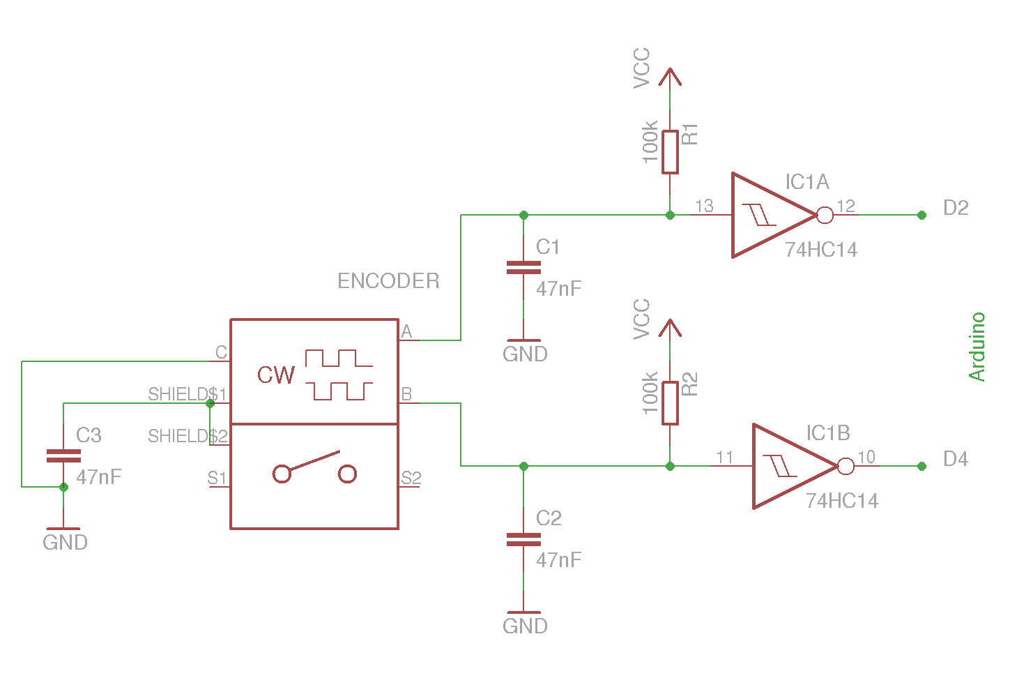
The example circuit and code should be sufficient to begin without delving into additional details. A rotary encoder is an electromechanical component with a shaft that records rotation and converts it into electrical pulses to indicate the direction of...
This humidity detector circuit diagram is straightforward and utilizes a limited number of components. It can be employed to activate electronic devices when the detector identifies a specific humidity level. The sensor is made from two copper pieces positioned...
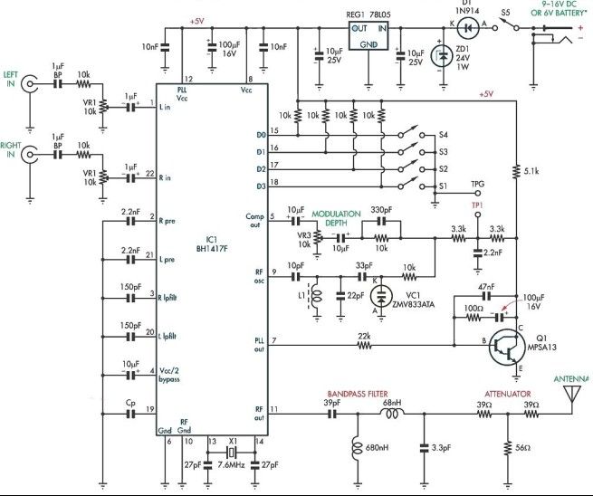
This stereo FM modulator circuit utilizes the BH1417F FM stereo transmitter integrated circuit (IC), which includes a stereo modulator for generating stereo composite signals and an FM transmitter for broadcasting an FM signal wirelessly. The stereo modulator produces a...
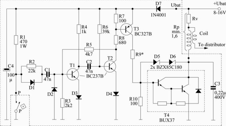
This scheme is designed for a four-cylinder engine. It aims to reduce fuel consumption, increase speed slightly, and minimize the need for frequent access to the distributor cap for contact button replacement, thereby saving costs. Transistors T1 and T2...