
Electronic keyer

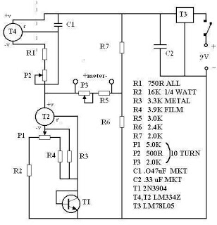
The circuit functions by utilizing capacitors C1 and C2 to create specific time delays that correspond to the duration of Morse code signals. The values of these capacitors, in conjunction with the resistors R1 and R2, allow for precise control over the timing characteristics of the generated signals. R1's role in setting the dot/dash ratio is crucial, as it defines the relative lengths of dots and dashes in Morse code, which are typically represented by short and long pulses, respectively.
R2's function as a speed regulator is equally important, as it adjusts the overall rate at which the Morse code is transmitted. By varying the resistance of R2, the operator can increase or decrease the transmission speed, accommodating different communication needs or preferences.
The inclusion of R5 as a relay drop-out point adds another layer of functionality to the circuit. This resistor sets a threshold at which the relay will disengage, effectively controlling how long the Morse code signals are maintained before the system resets or pauses. This feature is essential for ensuring that the circuit can operate in a loop, continuously generating Morse code signals without manual intervention.
Overall, the design of this circuit allows for a versatile and adjustable Morse code generator, making it suitable for various applications in communication systems where Morse code is utilized. The careful selection of component values will directly influence the performance and reliability of the generated Morse code signals.This circuit automatically produces Morse code dots and dashes set by time constants involving Cl and C2. Rl sets dot/dash ratio and R2 sets the speed R5 sets the relay drop-out point.
Related Circuits

This is the circuit diagram for an electronic door lock security key system. This security system circuit combines a pressed key mechanism (non-mechanical), and the output can be connected to drive a relay to unlock the door. The electronic door...
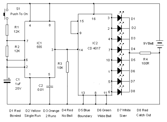
This electronic cricket device is a gift for children. This simple battery-powered circuit can be used to simulate a cricket match with friends. Each LED in the circuit represents various statuses of the cricket match, such as a six,...
This circuit generates a ringing sound akin to that produced by modern telephones. It comprises three nearly identical oscillators arranged in a sequence, each responsible for generating a square wave signal. The frequency of each oscillator is determined by...
There are many digital thermometers with ±1°C displays, but their accuracy is approximately ±1°C and they cannot be calibrated. A thermometer circuit was created using components available at a local electronics hobby shop, providing an educational experience. For a...

A simple lab power supply electronic project can be designed using this circuit diagram, which is based on the LM2576 monolithic integrated regulator that provides all the active functions for a step-down (buck) switching regulator. As seen in the...

Here is the circuit for a simple electronic delay detonator circuit diagram. The overall circuit is implemented in a hybrid IC module. The circuit includes a diode bridge connected to the input terminals, a power supply capacitor connected to...